For the very latest specifications visit www.aeroflex.com
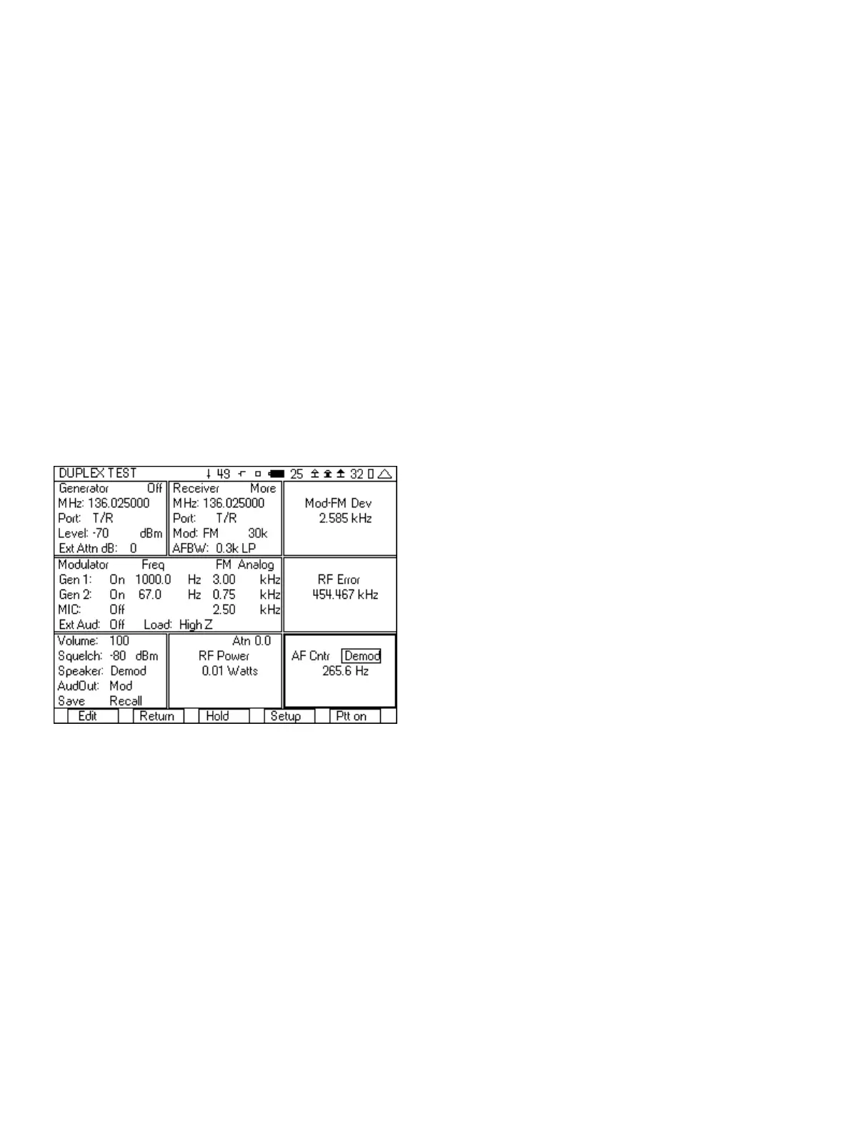
e. AFBW (Audio Frequency Bandwidth) should be set as
needed for the type of test. We want to measure the sub
audible tone frequency, so set this to 0.3k LP. This will
filter out everything except the tone squelch signal.
5. In the Modulator tile:
a. In the upper right hand corner, select Analog.
b. Set the modulation type to FM.
c. Set Gen1 to On 1000.0 Hz 3.00 kHz.
d. Set Gen2 to On and the deviation to 0.60 kHz.
e. The Gen2 frequency should be set to the frequency of the
tone squelch.
f. MIC and Ext Aud should be Off.
6. In the lower left hand tile:
a. Set Volume to 100.
b. Set the squelch level to -80 dBm.
c. Set the Speaker to Demod.
7. In the AF Cntr tile, move the cursor to the right and set the field
to Demod.
Figure 11 - Tone Squelch test setup
8. Key up the radio.
a. The Mod meter displays the amount of deviation of the
CTCSS tone.
b. The RF error meter displays the frequency error of the
radio.
c. The RF power meter displays the power level of the radio.
d. The AF Counter displays the frequency of the CTCSS tone.
9. Press the “Ptt On” softkey and you should hear a 1000 Hz tone in
the radio. If you do not hear a tone, then check the following.
a. Check to see if the CTCSS tone used matches the
expected CTCSS tone in the radio.
b. Make sure that the Generator frequency matches the
frequency of the radio under test.
After you have setup the 3500A for this test, you can save the setup
so that you do not need to go through these steps again. See the
section on Saving and Recalling setups for quick testing.
2.3 FM with DTMF Testing
The 3500A includes the capability of encoding and decoding DTMF
tones. This capability of encoding DTMF is part of the
modulator function and is selected from the upper right hand
corner of the Modulator tile. The decoding and display of the DTMF
digits is part of the DTMF tile, selected from the setup screen. The
following are the step by step instructions for setting up the 3500A
to encode and decode DTMF.
1. From the System menu, select the DUPLEX TEST screen.
2. Press the “Setup” softkey.
3. Place a 3 next to Modulation Meter, a 6 next to RF Error Meter,
an 8 next to RF Power Meter, and a 9 next to DTMF Decode.
4. Press the “Return” softkey.
5. In the Generator tile:
a. Enter the receive frequency of the radio.
b. Select the T/R port.
c. Enter RF Level (set to a nominal level, example uses -70).
d. Enter the cable loss or if using attenuator, the attenuator
loss.
e. Set the Generator to Off by pressing the far right softkey
(this key toggles the generator on and off).
6. In the Receiver tile:
a. Enter the transmit frequency of the radio.
b. Select the T/R port.
c. Select FM for Mod:
d. The value to the right of Mod is the selection for the
bandwidth of the signal. Make sure that this is greater than
the bandwidth of the signal from the radio. If this selection
is too narrow, the Modulation measurement will be wrong.
For this example it will be set to 30k.
e. AFBW (Audio Frequency Bandwidth) will be set to 0.3-5k
bp. This will bandpass the DTMF tones but filter out the
out of band noise.
7. In the Modulator tile
a. In the upper right hand corner select DTMF.
b. Set Gen1: to Off .
c. Set DTMF: to Burst.
d. Set the Hi deviation to 2.50 and the Lo deviation to
1.00 kHz .
e. Set Mark and Space to 100 ms.
8. Editing the DTMF digits field is unique from other fields on the
3500A because of the range of digits used for DTMF. The DTMF
field can contain from 1 to 10 DTMF digits. The range of valid
digits for DTMF is 0-9, A, B, C, D, # and *. The keypad is used to
enter the digits 0-9. Keypad 2 is also used for digits A, B and C,
7