4
As we have stated, there are four screens in the 3500A for
performing radio testing. Selecting one of these screens is
dependent on the type of testing that you want to perform. For
audio only testing you could select the AUDIO screen. If you are
only testing the receiver of a radio, then use the RECEIVER TEST
screen. If you are only testing the transmitter of a radio, then use the
TRANSMITTER TEST screen. But if you are testing transmitter and
receiver, then the best screen to select is the DUPLEX TEST screen.
The exception to this rule is when the DUPLEX TEST screen does
not have enough room for the meters that you need for your test
setup.
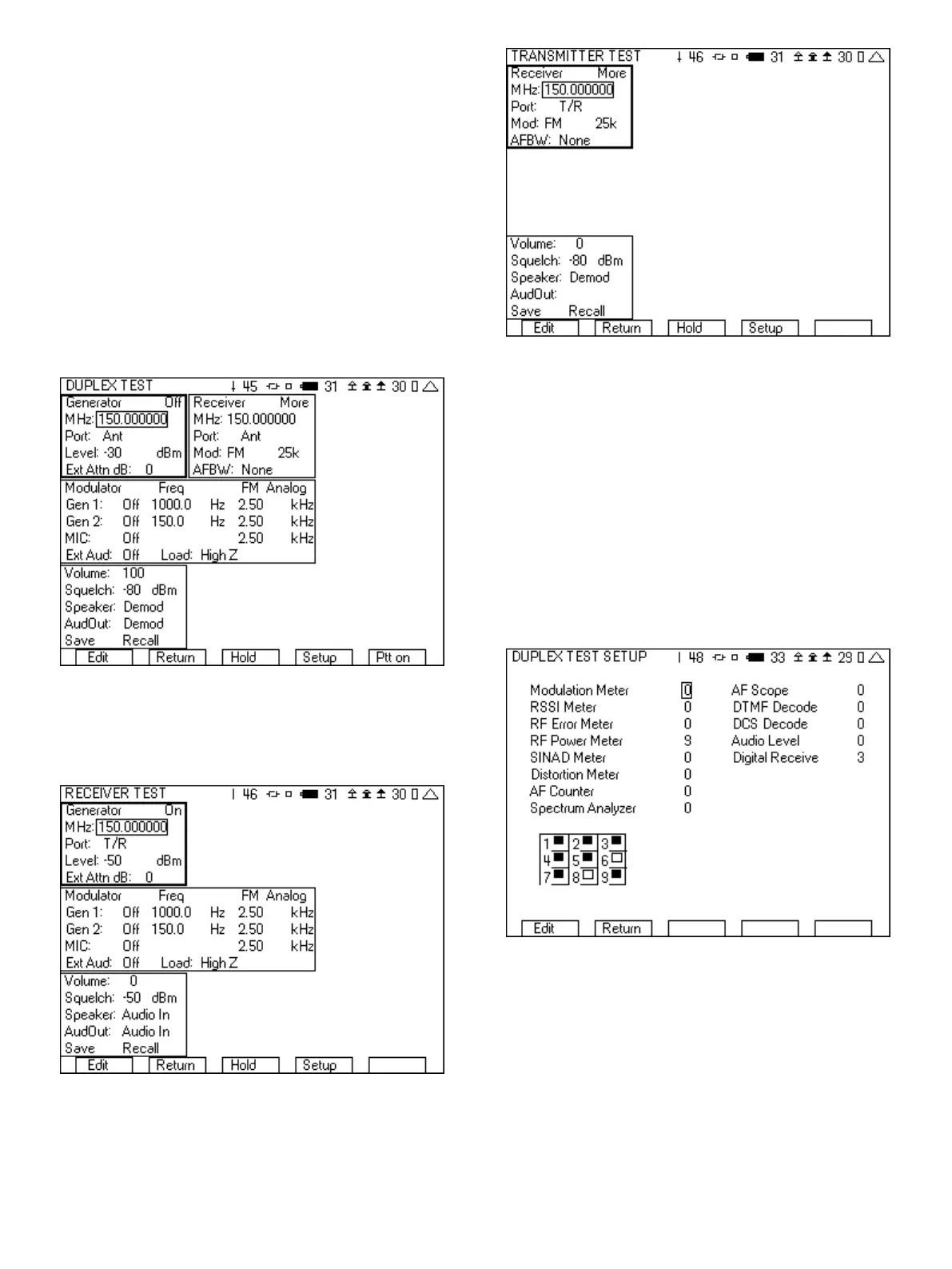
The DUPLEX TEST screen has room for four meters, with the rest of
the screen area already used for control of the generator, receiver,
modulator, and general setup. For many of your radio test scenarios,
you will find that four meters on the screen are sufficient. Figure 4
shows the DUPLEX TEST screen with no meters selected.
Figure 4 - Duplex test screen
The RECEIVER TEST screen has room for five meters since it does
not include a Receiver tile. Figure 5 shows the RECEIVER TEST
screen with no meters selected.
Figure 5 - Receiver test screen
The TRANSMITTER TEST screen has room for seven meters as it
does not include the Generator tile or the Modulator tile.
Figure 6 - Transmitter test screen
Adding meters and instruments to any of the radio test screens is
performed by selecting the “Setup” softkey. Pressing this key
switches to a screen that allows you to select the meters, including
the position, that you want to be part of your radio test screen.
Select the meter or instrument by putting a number next to it. The
number determines the position. You can remove a meter or
instrument by placing a 0 next to it. If you place a number next to a
meter or instrument for a tile that has already been used, then the
location will be replaced by the newly selected choice. The table in
the lower left hand corner illustrates the available locations on the
radio test screen. If the square in the table position has been
shaded in, then that position is currently being used. For example,
in Figure 7 position 6 and 8 are still available.
Figure 7 - DUPLEX TEST SETUP screen
1.2 Instrument Screens
Selections number 4, 6, 7 and 8 of the System screen enable
access to the stand alone instrument screens of the 3500A. Each
of these screens utilizes similar operational characteristics. Unlike
the radio test screens, these screens are not made up of tiles.
Instead, these screens are made up of a graphical display area and
a setup area. The right most softkey is used to change the fields that
are available in the setup area. The label of this softkey indicates
what the next set of fields in the setup area will be.