e. Set the Generator to “Off” by pressing the far right
softkey until the indication in the upper right hand
corner of the generator tile is “Off”.
6. In the Receiver tile
a. Set the frequency to be the same as the transmit
frequency of the radio.
b. Set the Port to T/R.
c. Set the Mod to DMR.
d. Move the cursor to the “More” field and press the Enter
softkey. You can now enter the value of the attenuator into
the atten field.
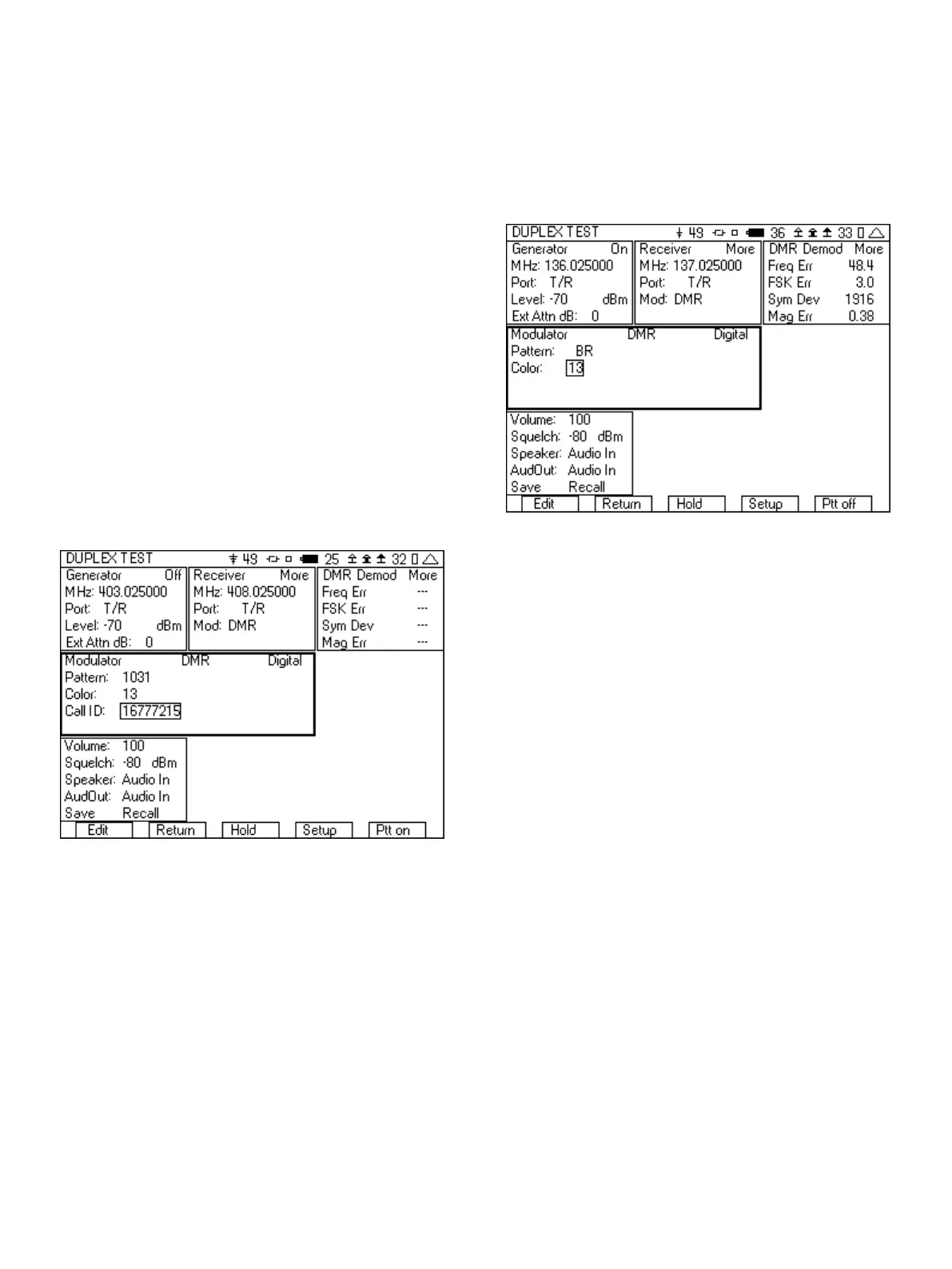
7. In the Modulator tile
a. In the upper right hand corner, select Digital.
b. Press the up arrow key and then from the list select DMR
(if not already selected).
c. For the pattern select the 1031.
d. Set the Color Code to match the color code of the radio
under test. If you don’t know the Color Code of this radio,
then we will try to determine it in step 10.
e. Set the Call ID to 16777215, the “all call” ID.
Figure 16 - DMR test setup
8. Connect an RF cable from the T/R port of the 3500A to the
Antenna of the radio.
9. Press the “Ptt on” softkey.
10. You should now hear the test tone in the radio. If you don’t hear
a tone, check the following.
a. Make sure that the Generator is on by observing the
indication in the upper right hand corner of the Generator
tile.
b. Check that the Generator frequency is set to the receive
frequency of the radio and that the RF Level is greater than
the sensitivity of the radio.
c. The Color Code must match the Color Code of the radio.
If you are not sure of the Color Code then slowly step
through all of the values. Do this by entering 0 into the
Color field. Then press “Edit” and step through the values
using the up arrow. If you allow a couple of seconds
between each increment, you should hear the tone on the
radio when the correct Color Code is found. Color Code
values range from 0-15.
11. Next change the pattern in modulator tile to BR. This pattern
simulates a Base Repeater and will provide the necessary
signal for the radio under test to synchronize with so that it can
transmit.
Figure 17 - DMR pattern set to BR
12. Key up the radio.
13. The DMR Demod tile should now be displaying Freq Err, FSK Err,
Sym Dev, and Mag Err.
a. Freq Err, FSK Err and Sym Dev are measurements of the
modulation fidelity. For more information on
understanding these measurements see the section on
Understanding the modulation fidelity parameters.
b. Mag Err is a measurement of the flatness of the level of the
power over the burst.
14. Move the cursor to the “More” field in the DMR Demod tile and
press the “Enter” softkey until you can view the High Pwr and
Low Pwr fields. The High Pwr field is the amount of power (in
dBm) in the slot that the radio is using. The Low Pwr field is the
amount of power in the off slot.
15. Move the cursor to the “More” field in the DMR Demod tile and
press the “Enter” softkey until you can view the Color and Call
ID decode field. This value should match the expected value for
the Color Code and Call ID from the radio under test. You can
also use this value for the Color and Call ID value in the
Modulator tile. The Radio ID value is also displayed.
16. If you have the capability and are able to use test software to
put the radio into test mode, you can also measure the BER of
the receiver and verify the sensitivity of the radio.
a. Put the radio into the test mode.
b. Select the O.153 pattern in the modulator tile of the
3500A.
c. Select the random data pattern in the test application.
d. In the Generator tile, set the frequency to match the
receive frequency of the radio under test.
12