22
Trace Page Features
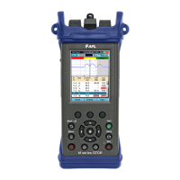
The illustration below and table on the next page describe the Trace Page features (example trace
below includes a launch and receive cable).
Event Table displays OTDR
event measurements
Information Page
displays OTDR setup
parameters, launch
and receive cable
data, and event
thresholds
Summary Page
displays end-to-end
link measurements
File name (cable
name + ber
number), or “New
Trace” if le has not
been saved
Test Wavelengths
(RED is current)
Grid units display
dB/div on vertical
axis and distance/div
on horizontal axis
Trace Page displays OTDR trace, A/B cursors,
Loss, Distance, and max reectance between
A and B cursors
A and B cursors
Trace graph (RED is
current)
Receive cable
Note: this region is
only present if the
network was dened
(in the Cables page)
to include a Receive
cable. The width of the
shaded receive region
is based on the length
of the receive cable
specied in the Cables
page.
Launch cable
Note: this region is
only present if the
network was dened
(in the Cables page)
to include a Launch
cable. The width of the
shaded region is based
on the length of the
launch cable specied
in the Cables page.
Fiber under test
2-point Loss between
A and B cursor
B cursor location
(active cursor is
highlighted)
Distance between A
and B cursor
For multi-wavelength
tests, press to toggle
active trace
A cursor location
Maximum
Reectance between
A and B cursor
Press to toggle Zoom and Move mode. In Move mode,
the key label will be displayed as [ Zoom]. In Zoom
mode, the key label will be displayed as [
x
Zoom]
Press to Unzoom or
Rezoom
Soft key labels