Appendix A 77
Agilent 4072/4073 Preinstallation Guide, Edition 4
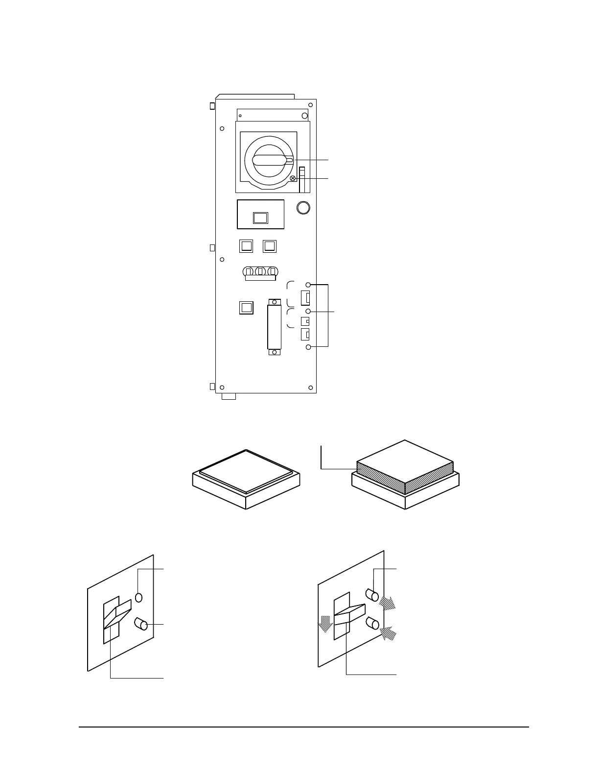
Confirming the System Power Safety
Component Location for PDU and Checking EMO
Figure 4-6 PDU component locations
Figure 4-7 Positions of circuit protector (EMO and fan protectors)
Figure 4-8 Positions of GFCI indicator
~LINE
System Sw
Fan Protector
Emargency Breaker
EMO
Protector
Cabinet
Fan
Testh ead
Fan
Error
Error
Emargency
Interface
Over
Voltage
LEDs
disconnect device
door lock
release screw
yellow
main breaker on position
breaker test switch
GFCI in position
white
gray
main breaker middle position
GFCI out position
white