14. Remove
the triaxial
connector.
Note
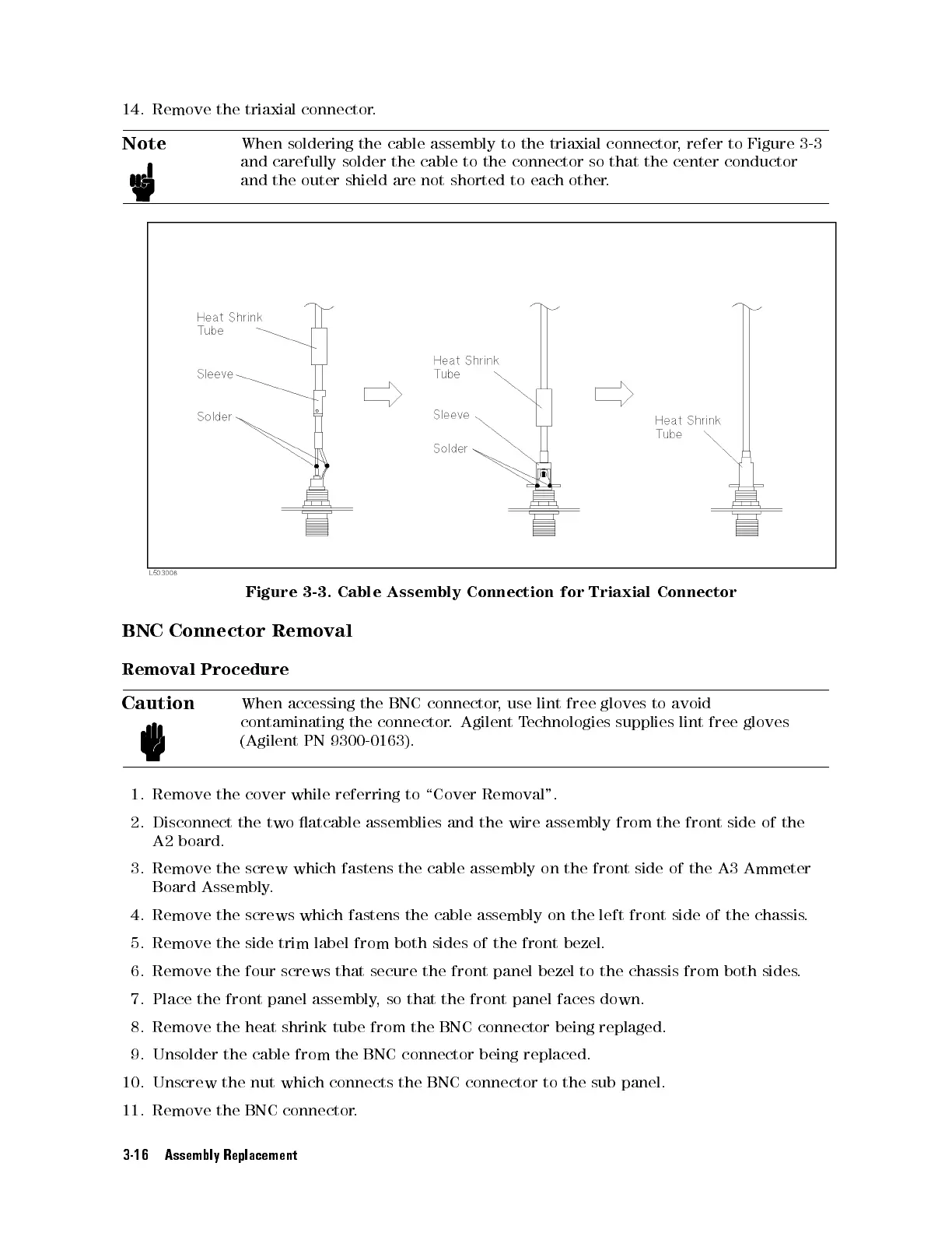
When
soldering
the
cable
assembly
to
the triaxial
connector,
refer to
Figure 3-3
and
carefully
solder
the
cable to
the connector
so that
the center
conductor
and
the
outer
shield
are not
shorted to
each other
.
Figure
3-3.
Cable
Assembly
Connection
for
Triaxial
Connector
BNC
Connector
Removal
Removal
Procedure
Caution
When
accessing
the
BNC
connector
,
use
lint
free
gloves
to
avoid
contaminating
the
connector
.
Agilent
T
echnologies
supplies lint
free gloves
(Agilent
PN
9300-0163)
.
1.
Remove
the
cover
while
referring
to
\Cover
Removal".
2.
Disconnect
the
two
atcable
assemblies
and
the
wire
assembly from
the front
side of
the
A2
board.
3. Remove the screw which fastens the cable assembly on the front side of the A3 Ammeter
Board Assembly
.
4. Remove the screws which fastens the cable assembly on the left front side of the chassis
.
5. Remove the side trim label from both sides of the front bezel.
6. Remove the four screws that secure the front panel
bezel to the chassis from both sides
.
7. Place the front panel assembly, so that the front panel faces down.
8. Remove the heat shrink tube from the BNC connector being replaged.
9. Unsolder the cable from the BNC connector being replaced.
10. Unscrew the nut which connects the BNC connector to the sub panel.
11. Remove the BNC connector.
3-16 Assembly Replacement
 Loading...


