Digital
Section
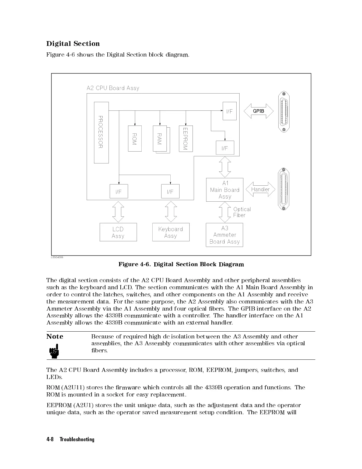
Figure
4-6
shows
the
Digital
Section
block
diagram.
Figure
4-6.
Digital
Section
Block
Diagram
The
digital
section
consists
of the
A2 CPU
Board Assembly
and
other
peripheral
assemblies
such
as
the
keyboard
and LCD
. The
section communicates
with
the
A1
Main
Board
Assembly
in
order
to
control
the
latches,
switches,
and other
components on
the
A1
Assembly
and
receive
the
measurement
data.
F
or the
same purpose
,the
A2 Assembly
also
communicates
with
the
A3
Ammeter
Assembly
via the
A1 Assembly
and four
optical bers
.The
GPIB interface
on
the
A2
Assembly
allows
the
4339B
communicate
with
a controller
.
The
handler
interface
on
the
A1
Assembly allows the 4339B communicate with an
external handler
.
Note
Because of required high dc isolation between the A3 Assembly and
other
assemblies, the A3 Assembly communicates with other assemblies via optical
bers.
The A2 CPU Board Assembly includes a processor
, ROM, EEPROM, jumpers
, switches
, and
LEDs.
ROM (A2U11) stores the rmware which controls all the 4339B operation and functions. The
ROM is mounted in a socket for easy replacement.
EEPROM (A2U1) stores the unit unique data, such as the adjustment data and the operator
unique data, such as the operator saved measurement setup condition. The EEPROM will
4-8 Troubleshooting
 Loading...


