62 Maintenance
3 Maintenance
4
Remove the valve thermal enclosure. See “To Remove the
Valve Thermal Enclosure”.
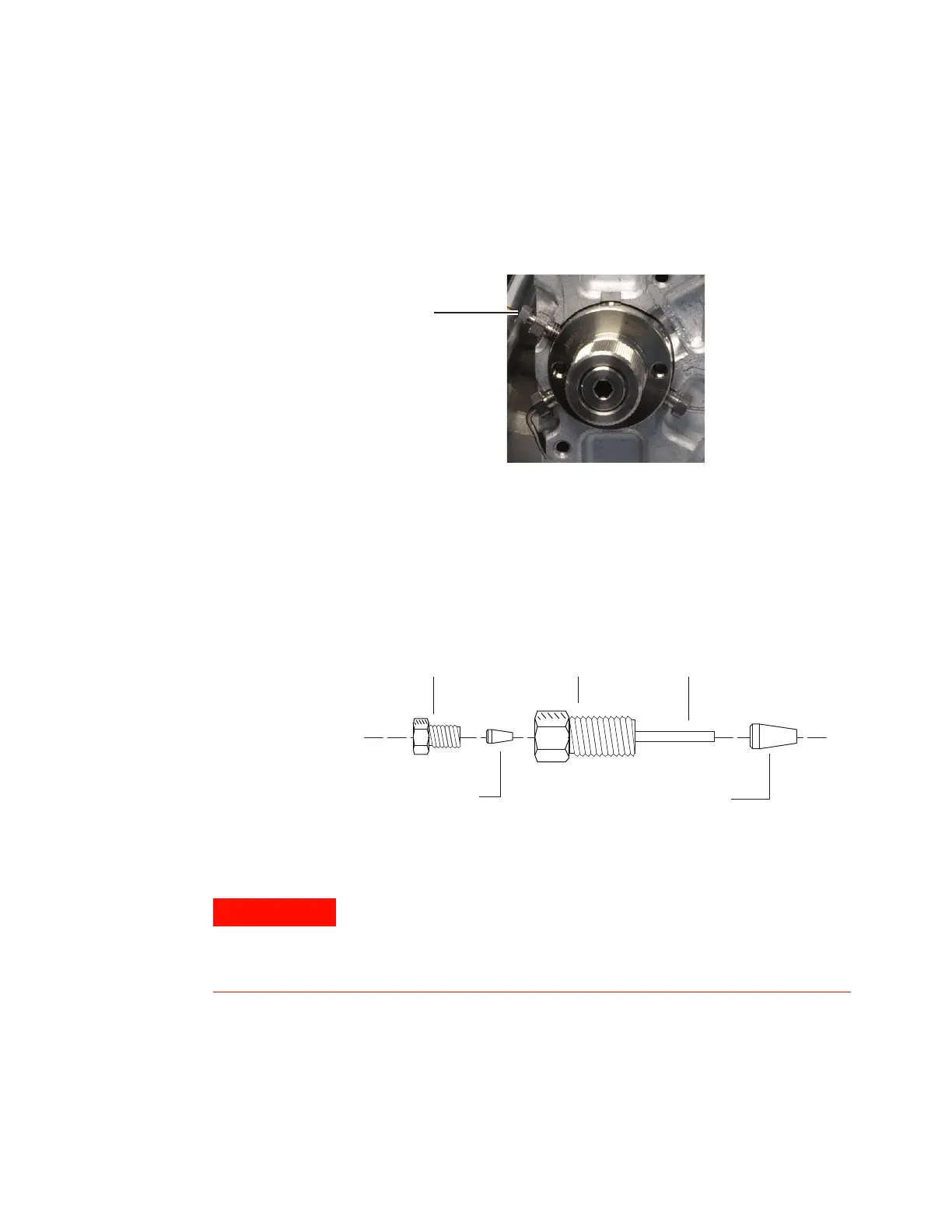
5 The transfer line will install in valve port 3 (at the 10
O’clock position), as shown in Figure 35.
Figure 35 Valve Port 3
The transfer line installs using a 1/16- inch internal
reducer, as shown in Figure 36. If possible, leave the
existing 1/4- inch nut and ferrule in place and install the
new fused silica into it using a new ferrule and the
existing 3/16- inch nut.
Figure 36 Internal reducer parts
3/16-inch nut
Polyimide ferrule
1/4-inch nut
Stainless steel ferrule
1/16-inch tube
Wear safety glasses to protect your eyes from flying particles
while handling, cutting, or installing glass or fused silica capillary
columns. Use care in handling these columns to prevent puncture
wounds.

 Loading...


