7- 45
Operating Concepts
Measurement Calibration
known at all frequencies.
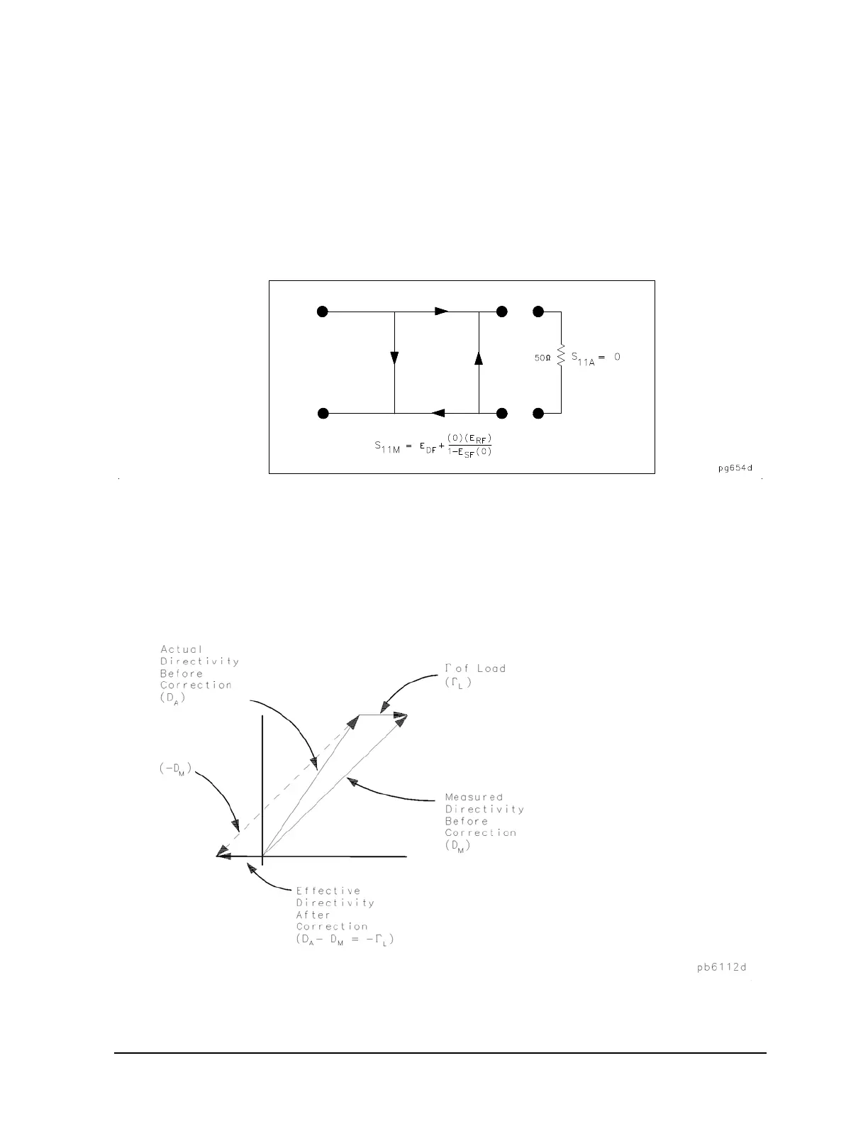
The first standard applied is a "perfect load," which makes S
11A
= 0 and essentially measures directivity.
See
Figure 7-29. "Perfect load" implies a reflectionless termination at the measurement plane. All incident
energy is absorbed. With S
11A
= 0 the equation can be solved for E
DF
, the directivity term. In practice, of
course, the "perfect load" is difficult to achieve, although very good broadband loads are available in the
compatible calibration kits.
Figure 7-29 "Perfect Load" Termination
Since the measured value for directivity is the vector sum of the actual directivity plus the actual reflection
coefficient of the "perfect load," any reflection from the termination represents an error. System effective
directivity becomes the actual reflection coefficient of the near "perfect load" as shown in
Figure 7-30. In
general, any termination having a return loss value greater than the uncorrected system directivity reduces
reflection measurement uncertainty.
Figure 7-30 Measured Effective Directivity

 Loading...


