7- 47
Operating Concepts
Measurement Calibration
Device Measurement
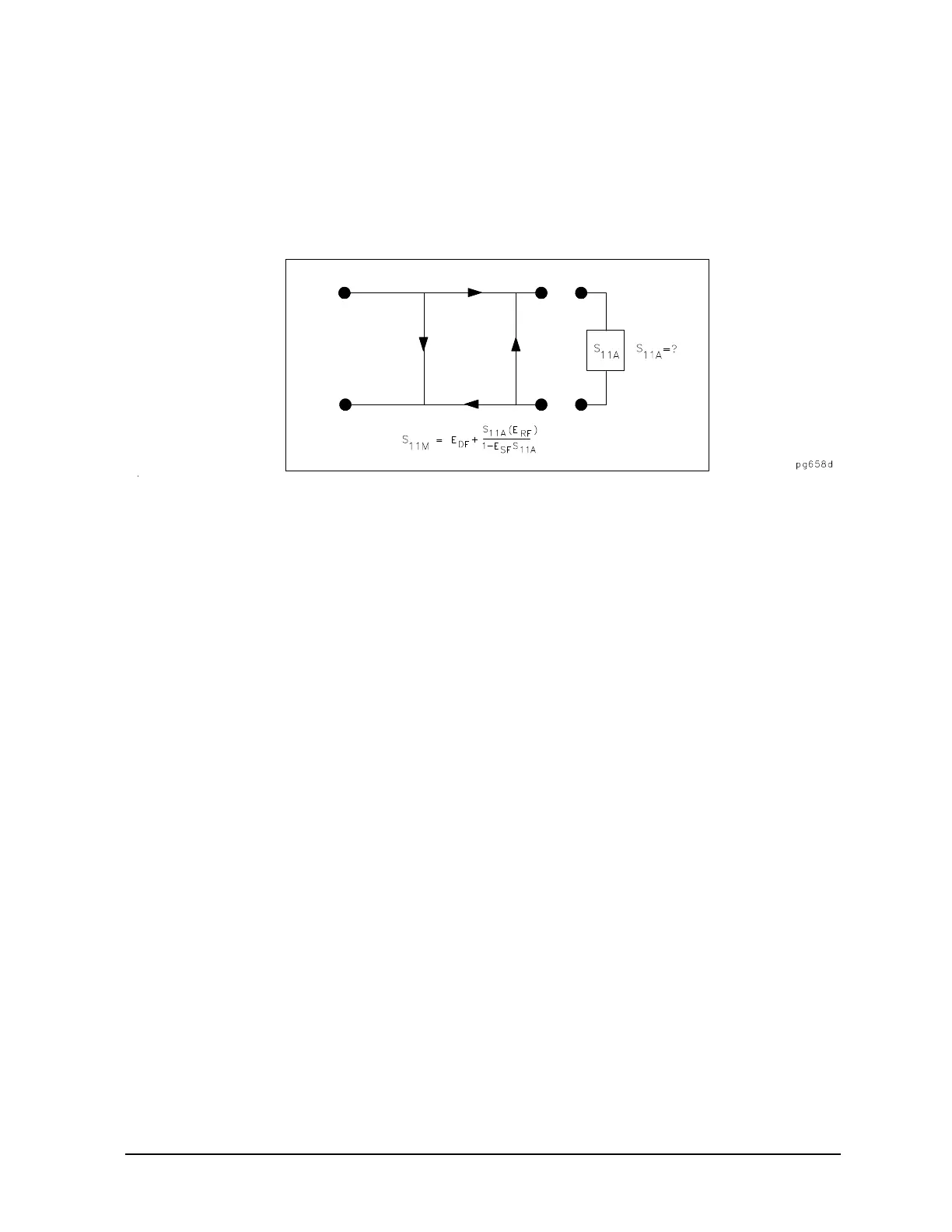
Now the unknown is measured to obtain a value for the measured response, S
11M
, at each frequency. Refer
to
Figure 7-33.
Figure 7-33 Measured S
11
This is the one-port error model equation solved for S
11A
. Since the three errors and S
11M
are now known for
each test frequency, S
11A
can be computed as follows:
For reflection measurements on two-port devices, the same technique can be applied, but the test device
output port must be terminated in the system characteristic impedance. This termination should have as low
a reflection coefficient as the load used to determine directivity. The additional reflection error caused by an
improper termination at the test device's output port is not incorporated into the one-port error model.
Two-Port Error Model (ES Models Only)
The error model for measurement of the transmission coefficients (magnitude and phase) of a two-port
device is derived in a similar manner. The potential sources of error are frequency response (tracking),
source match, load match, and isolation as shown in
Figure 7-34. These errors are effectively removed using
the full two-port error model.
S
11A
S
11M
E
DF
–
E
SF
S
11M
E
DF
–
E
RF
+
-----------------------------------------------------------=

 Loading...


