Return Loss Measurement Return Loss Measurement
Agilent 8163A/B, 8164A/B & 8166A/B Mainframes, Sixth Edition 181
3 Move to [RLref], press [Edit]. Make sure that the displayed value of [RLref] is
correct. If it is not, move to [RLref], press [Edit], set the value the return loss
value of the reference cable you are using, then press [OK].
4 Switch on the Laser.
5 Press [Menu]. Move to <Reflectance calibration> and press Enter. The
instrument measures the power reflected by the reference cable. The [RL] value
changes to the same value as entered for [RLref].
Front Panel Delta Calibration
For higher accuracy we recommend that you also calibrate for Front Panel
Delta. This is the difference between the insertion loss of the reference
cable, and the insertion loss of the patchcord used for return loss
measurement.
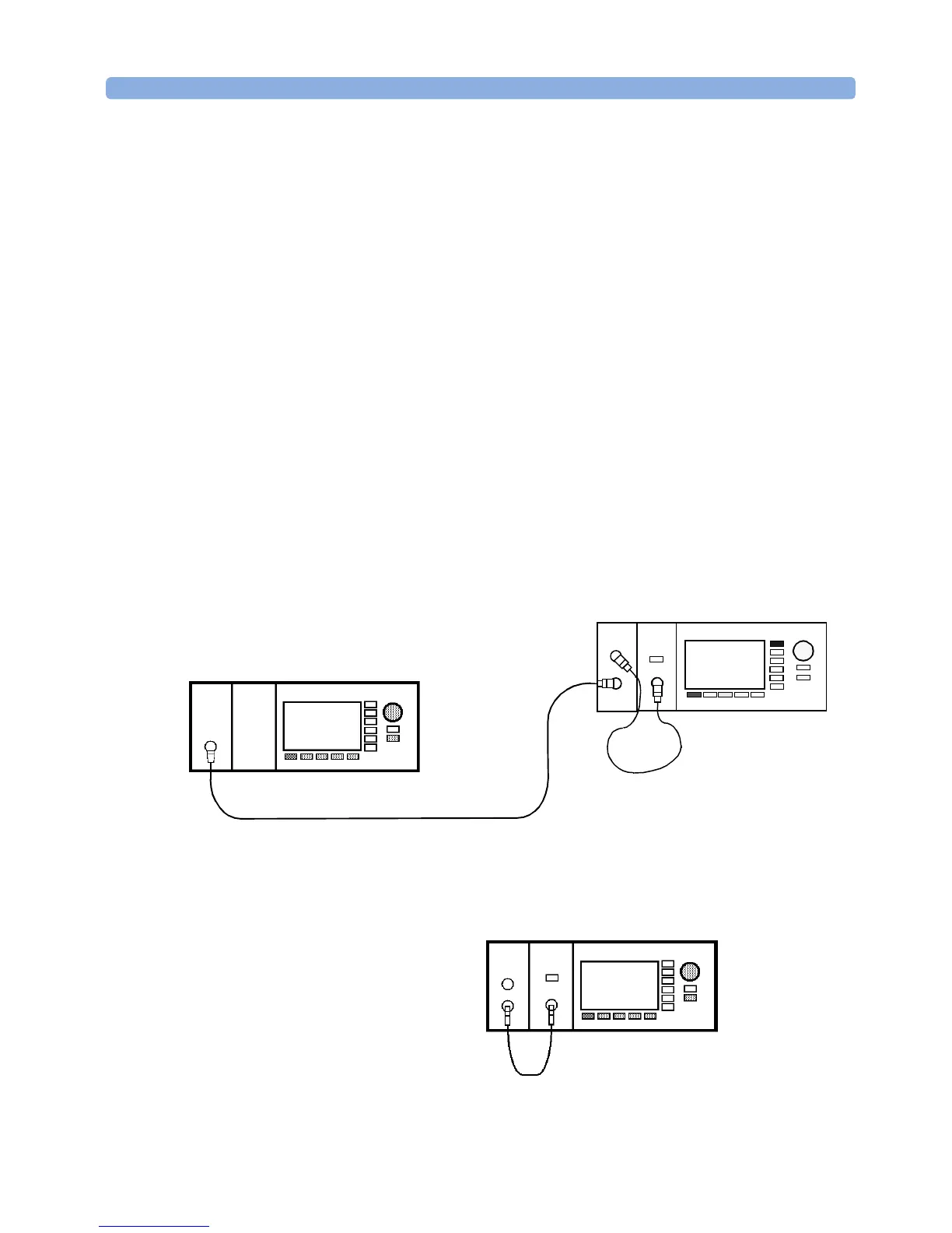
Measuring the Power Transmitted Through the Reference Cable
First, measure the power transmitted through the reference cable.
1 Making sure all the connectors are clean, set up the instrument as shown in
Figure 100 if you are using an External Source.
Figure 100 Power Transmitted through the Reference Cable - External Source
or Figure 101 if you are using an internal source
(Agilent 81611A/2A/3A/4A Return Loss modules only).
Figure 101 Power Transmitted through the Reference Cable - Internal Source
Agilent 81610CC Reference Cable
Power
Sensor
8163B Lightwave Multimeter
8161x 8163B Lightwave MultimeterLaser
Source
Agilent 81113PC
Sensor
8161x
Power
8163B Lightwave Multimeter
Agilent 81610CC
Reference Cable
 Loading...


