Input and Output Connectors Installation and Maintenance
Agilent 8163A/B, 8164A/B & 8166A/B Mainframes, Sixth Edition 311
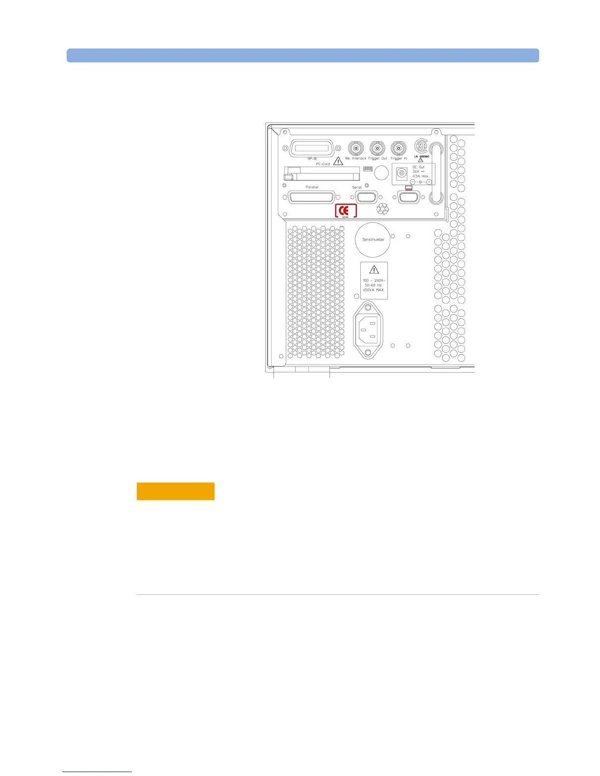
Figure 199 Rear Panel of the Agilent 8166B Lightwave Multichannel System
The Remote Interlock (RIL) connector
There is a Remote Interlock (RIL) connector at the back of the
Agilent 8163A/B Lightwave Multimeter System, Agilent 8164A/B
Lightwave Measurement System, and Agilent 8166A/B Lightwave
Multichannel System for the purpose of the optional connection of a
foot pedal. Setting the trigger configuration is explained in
“Additional Information” on page 63. If the short circuit at this BNC
connector is opened, the laser is switched off immediately and
cannot be switched on until it is closed again.
CAUTION
 Loading...


