Installation and Maintenance Input and Output Connectors
310 Agilent 8163A/B, 8164A/B & 8166A/B Mainframes, Sixth Edition
Input and Output Connectors
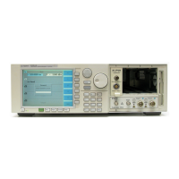
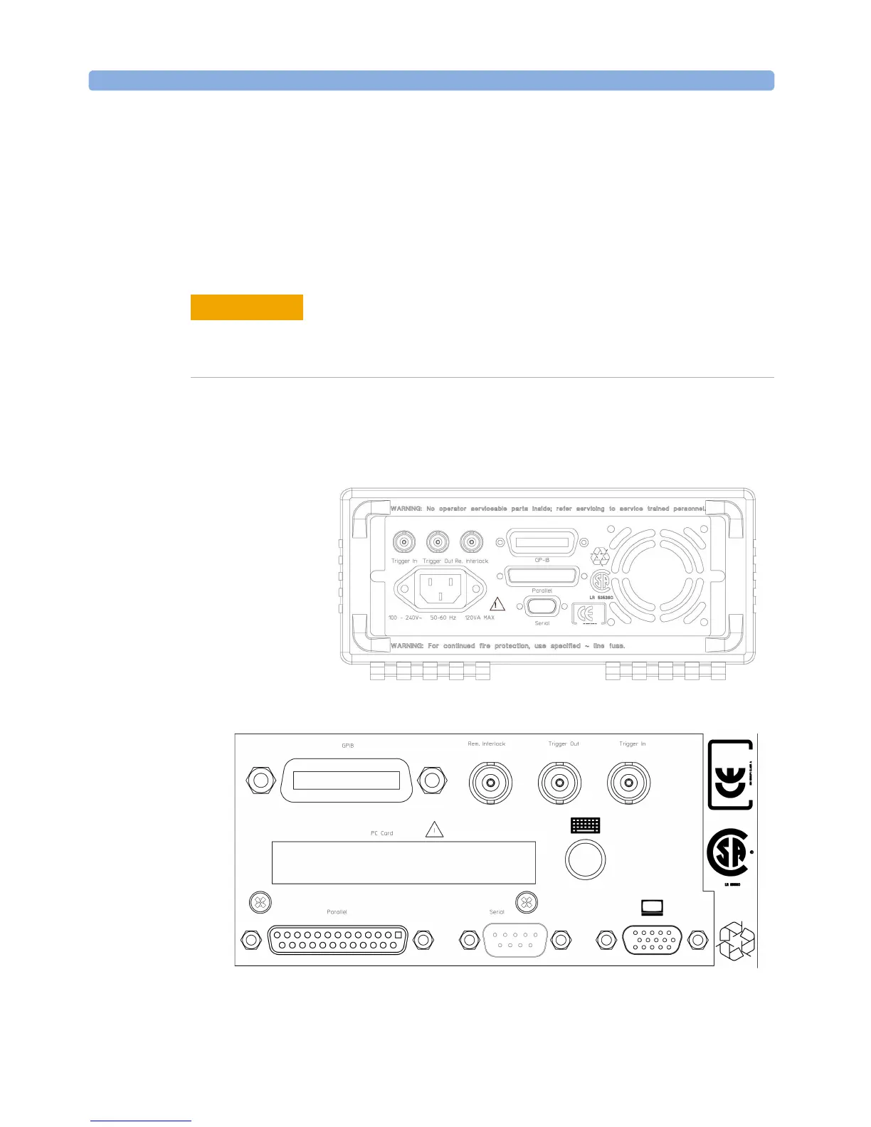
There are three BNC connectors on the rear panel of your instrument.
These are the Remote Interlock, the Trigger Out and the Trigger In
connectors.
There is one output BNC connector: the Trigger Output, see Figure 197 or
Figure 197 . This is a TTL output. Do not apply an external voltage to this
connector.
Figure 197 Rear Panel of the Agilent 8163B Lightwave Multimeter System
Figure 198 Rear Panel of the Agilent 8164B Lightwave Measurement System
There are two input BNC connectors: the Remote Interlock Connector and
the Trigger Input, see Figure 197 or Figure 197 . These are TTL inputs. A
maximum of 5 V can be applied as an external voltage to either of these
input connectors.
CAUTION
 Loading...


