Chapter 7 Tutorial
Output Characteristics
146
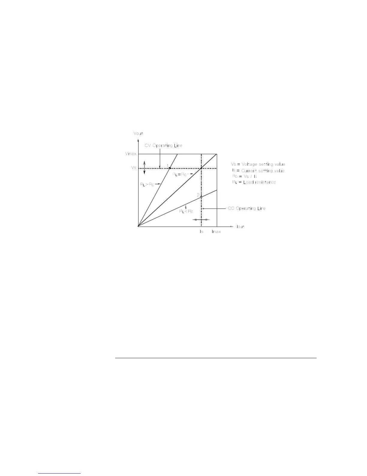
Figure 7-5 shows the operating modes of the three outputs of the Agilent E3631A
power supply. The operating point of one supply will be either above or below the
line R
L
= R
C
. This line represents a load where the output voltage and the output
current are equal to the voltage and current setting. When the load R
L
is greater than
R
C
, the output voltage will dominate since the current will be less then the current
setting. The power supply is said to be in constant-voltage mode. The load at point 1
has a relatively high resistance value (compared to R
C
), the output voltage is at the
voltage setting, and the output current is less than the current setting. In this case the
power supply is in the constant-voltage mode and the current setting acts as a current
limit.
Figure 7-5. Output Characteristics
When the load R
L
is less than R
C
, the output current will dominate since the voltage
will be less than the set voltage. The power supply is said to be in constant-current
mode. The load at point 2 has a relatively low resistance, the output voltage is less
than the voltage setting, the output current is at the current setting. The supply is in
constant-current mode and the voltage setting acts as a voltage limit.