Chapter 1 General Information
Description
20
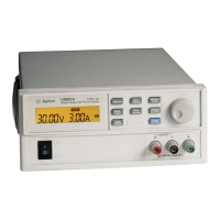
The front panel includes a VFD for displaying the output voltage and current. Two
4-digit voltage and current meters accurately show the actual or limit values of a
selected supply simultaneously. Three meter selection keys choose the voltage and
current of any one output to be monitored on the display.
Connections to the power supply's output and to chassis ground are made to binding
posts on the front panel. The +25V and -25V supply's outputs share a common output
terminal which is isolated from chassis ground. The positive and negative terminals
of each output can be grounded, or each output can be kept within ±240 Vdc from the
chassis ground. The power supply is shipped with a detachable, 3-wire grounding
type power cord. The ac line fuse is an extractor type on the rear panel.
The power supply can be calibrated from the front panel directly or with a controller
over the GPIB or RS-232 interface using calibration commands. Correction factors
are stored in non-volatile memory and are used during output programming.
Calibration from the front panel or a controller eliminates the need to remove the top
cover or even the need to remove the power supply from your system cabinet. You
can guard against unauthorized calibration by using the “Secured” calibration
protection function.