Chapter 4 47
Troubleshooting
Function Specific Troubleshooting
4. Troubleshooting
Step 4. Replace the handler interface board.
Step 5. Turn the E4980A ON.
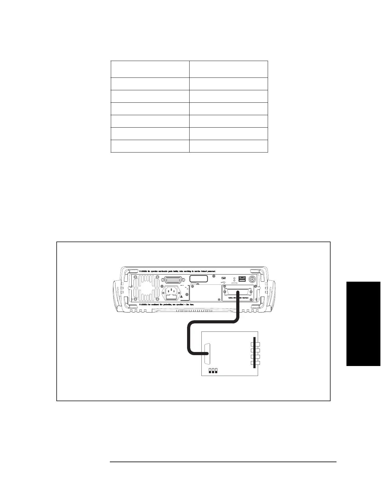
Step 6. Connect the handler interface connector on the E4980A’s rear panel to the handler
simulator as shown in
Figure 4-10.
Figure 4-10 Handler Interface Function Test Setup
Step 7. Press [System].
Step 8. Press the SELF TEST softkey to display the SELF TEST page.
3 On
4 Off
5 Off
6 Off
7 N.A.
8 N.A.
*1.The bit numbers referenced in this table are the numbers
printed on the bit switch (S1) of the handler interface
board.
Table 4-8 Bit switch (S1) settings
Bit number
*1
Factory default settings
㪼㪋㪐㪏㪇㪸㫊㪼㪈㪇㪌㪇
USB
LAN
Trigger
GPIB
LINE
115V
-230V
50/60Hz
150VA MAX
Fuse
T3A , 250V
E4980A
Serial Label
Option 710: No Interface
E4980A
Handler Simulator

 Loading...


