Verification and Calibration Appendix B
Series N6700 User’s Guide 155
Front Panel: SCPI Command:
Select
System\Admin\Cal\Function\CMRR.
Then select Next.
CAL:VOLT:CMRR (@1)
*OPC?
Current Programming and Measurement Calibration
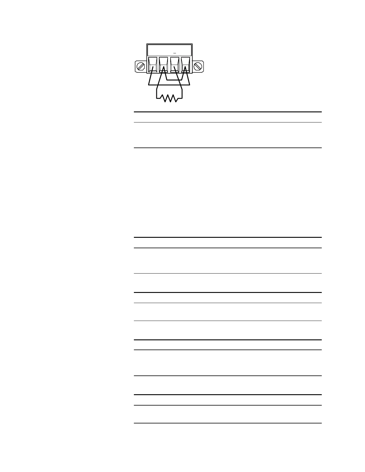
Step 18. Connect the +sense terminal to the +output, and the -sense terminal
to the –output. Connect a precision shunt resistor to the output. The
shunt resistor should be able to measure at least 120% of the output’s
rated full-scale current. Connect the DVM across the shunt resistor.
Step 19. Select the full-scale current programming range. The following
example selects the 10 amp full-scale current programming and
measurement range of channel 1. The value to program a range must
be the maximum current of the range.
Front Panel: SCPI Command:
Select
System\Admin\Cal\Function\Iprog
Then select the High range.
CAL:CURR 10, (@1)
Step 20. Select the first current calibration point.
Front Panel: SCPI Command:
Select Next. The information field
should indicate: Enter P1 data
CAL:LEV P1
*OPC?
Step 21. Calculate the shunt current (I=V/R) and enter the data.
Front Panel: SCPI Command:
Select the Measured Data field. Enter
the data from the external DVM.
Press Select when done.
CAL:DATA <data>
Step 22. Select the second current calibration point.
Front Panel: SCPI Command:
Select Next. The information field
should indicate: Enter P2 data
CAL:LEV P2
*OPC?
25 Ohm
Resistor
+S + -S
 Loading...