Service Appendix D
Series N6700 User’s Guide 173
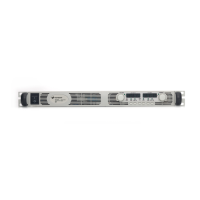
Step 3. To install a module, align the module over the alignment pins, and
push it down onto the mainframe connector.
Step 4. Fasten the module to the mainframe. Install the two screws from the
power module or filler module at either end of the module.
Step 5. Replace the blower cover when finished.
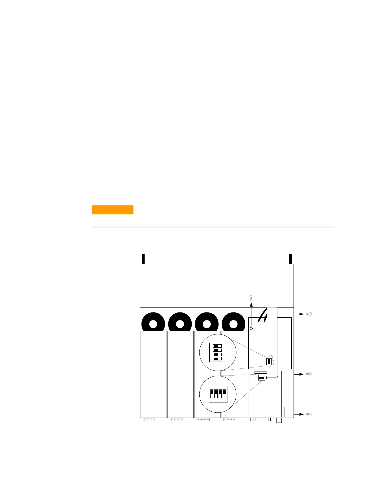
Accessing the Calibration switch
Step 1. Remove the blower cover. Remove three screws from the top of the
cover and two screws on the sides. Tilt the cover up and slide it out.
Step 2. Remove the interface cover. Remove the three screws along the left
side of the unit. Then remove the screw at the front of the cover. Lift
off the cover.
Step 3. The calibration switch is on the interface board near the ribbon
cable. (On Agilent N6700A mainframes, the switch is located under
the ribbon cable on the carrier board.) To change the calibration
switch settings, use a small screwdriver to move the switches. Refer
to Appendix B for settings information.
CAUTION
Do not use a pencil to move the switches. Any graphite dust that gets on the
switches will conduct electricity.
Step 4. Replace all covers when finished.
1 2 3 4
ON
1 2 3 4
ON
N6700A
N6700B
 Loading...