2 Installation
22 Series N6700 User’s Guide
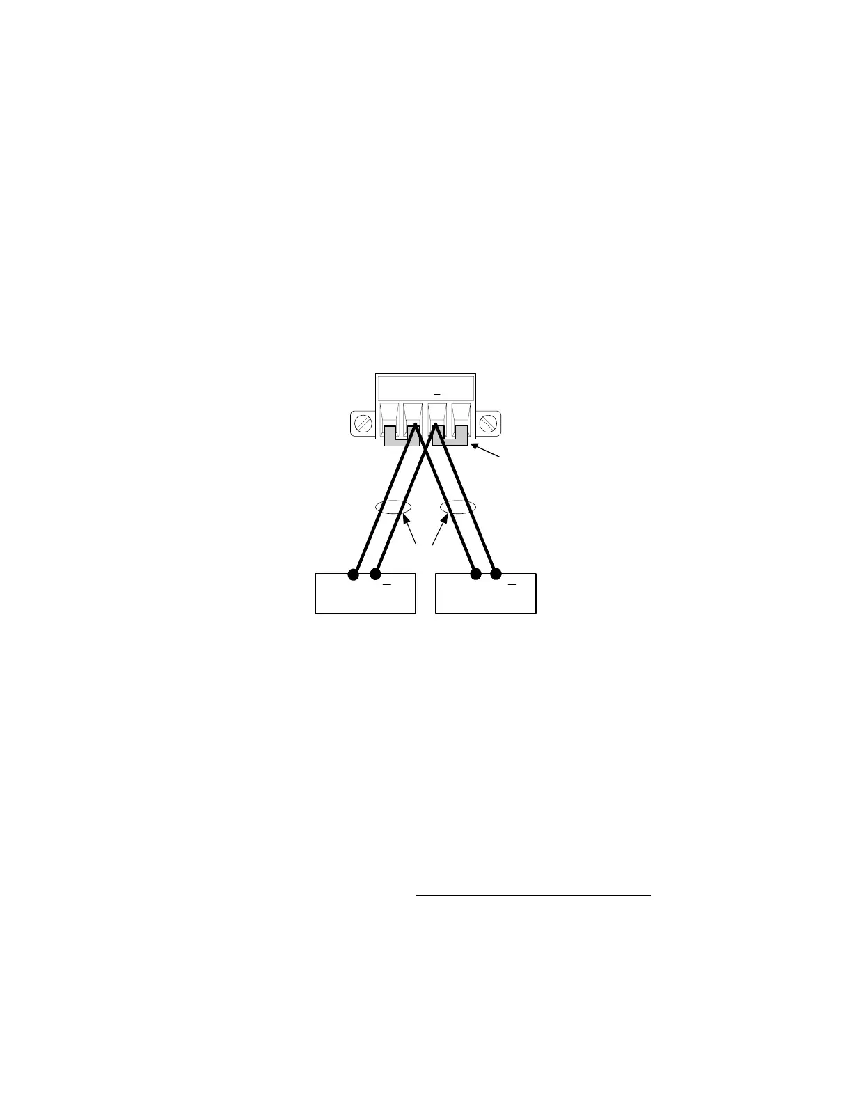
Multiple Loads
If you are using local sensing and are connecting multiple loads to
one output, connect each load to the output terminals using separate
connecting wires (see the figure below). This minimizes mutual
coupling effects and takes full advantage of the power system's low
output impedance. Each pair of wires should be as short as possible
and twisted or bundled to reduce lead inductance and noise pickup.
If load considerations require the use of distribution terminals that
are located away from the instrument, connect the output terminals
to the remote distribution terminals by a pair of twisted or bundled
wires. Connect each load to the distribution terminals separately.
Remote voltage sensing is recommended under these circumstances.
Sense either at the remote distribution terminals or, if one load is
more sensitive than the others, directly at the critical load.
Positive and Negative Voltages
Either positive or negative voltages can be obtained from the output
by grounding (or "commoning") one of the output terminals. Always
use two wires to connect the load to the output regardless of where
or how the system is grounded. The instrument can be operated with
any output terminal ± 240 VDC including output voltage from ground.
Response Time with an External Capacitor
When programming with an external capacitor, voltage response time
may be longer than that specified in Appendix A. Use the following
formula to estimate the additional response time for up
programming:
Response Time = (Added Output Capacitor)X(Change in Vout)
Current Limit Setting
Note that programming into an external output capacitor may cause
the power system to briefly enter constant current or constant power
operating mode, which adds additional time to the estimation.
+S + -S
LOAD
TWIST LEADS
LOAD
+ +
SENSE JUMPERS
INSTALLED FOR
LOCAL SENSING
 Loading...