Installation 2
Series N6700 User’s Guide 23
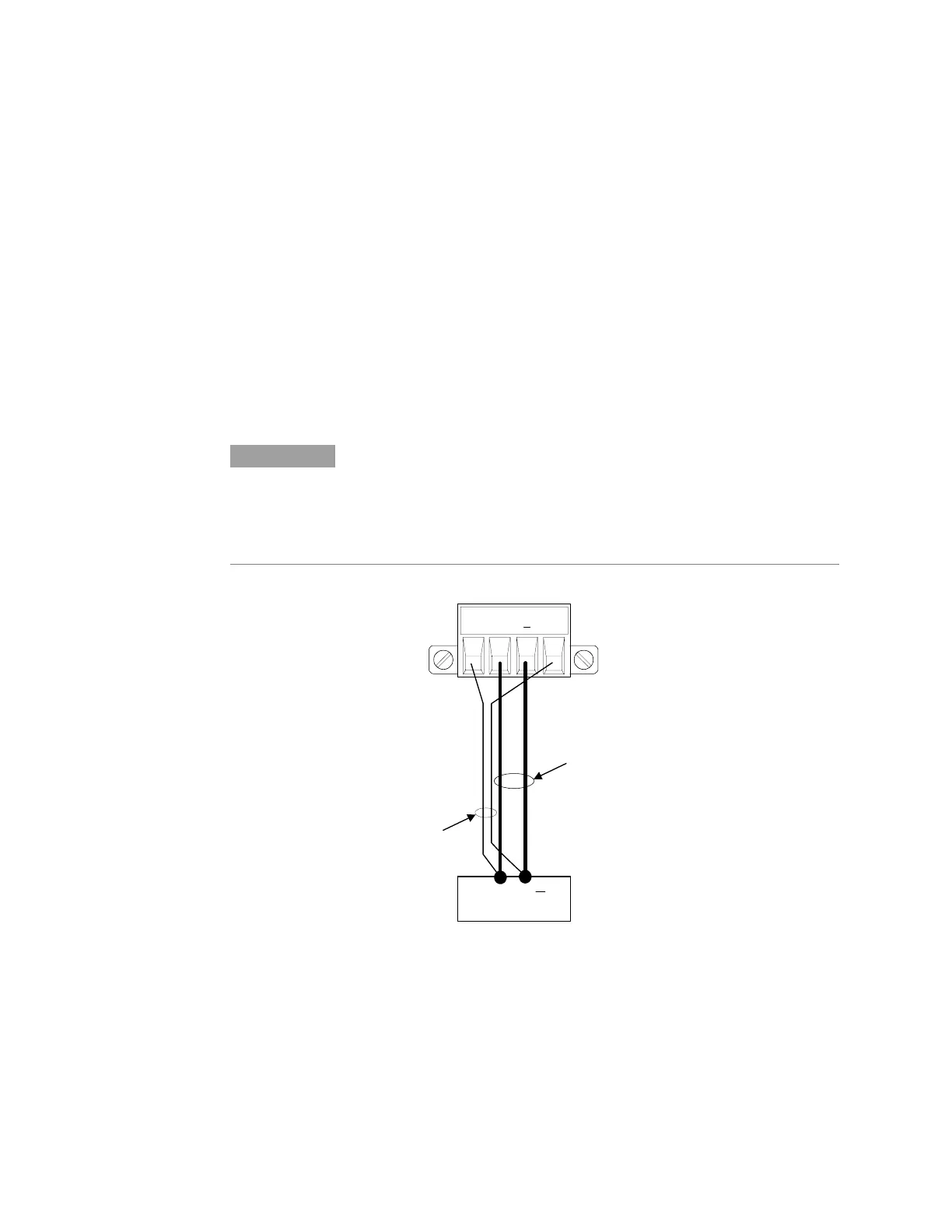
Remote Voltage Sensing
Because of the unavoidable voltage drop developed in the load leads,
the terminal block strapping patterns discussed thus far do not
provide the best possible voltage regulation at the load. The remote
sensing connections shown in the figure below improve the voltage
regulation at the load by monitoring the voltage there instead of at
the output terminals. This allows the power system to automatically
compensate for the voltage drop in the load leads.
Remote sensing is especially useful for CV operation with load
impedances that vary or have significant lead resistance. It has no
effect during CC operation. Because sensing is independent of other
power system functions, remote sensing can be used regardless of
how the power system is programmed. Note that with remote
sensing, the voltage readback circuit monitors the load voltage
through the sense terminals.
NOTE
The OVP circuit senses at the main output terminals and not through the sense
terminals. Due to the voltage drop in the load leads, the voltage sensed by the
OVP circuit could be higher than the voltage being regulated at the load.
Therefore, you must take into account the additional voltage drop in the load
leads when setting the over-voltage trip point.
TWIST PAIR
+S + -S
TWIST LEADS
LOAD
+
 Loading...