34 Installation Note E4440-90613
Installation Procedure
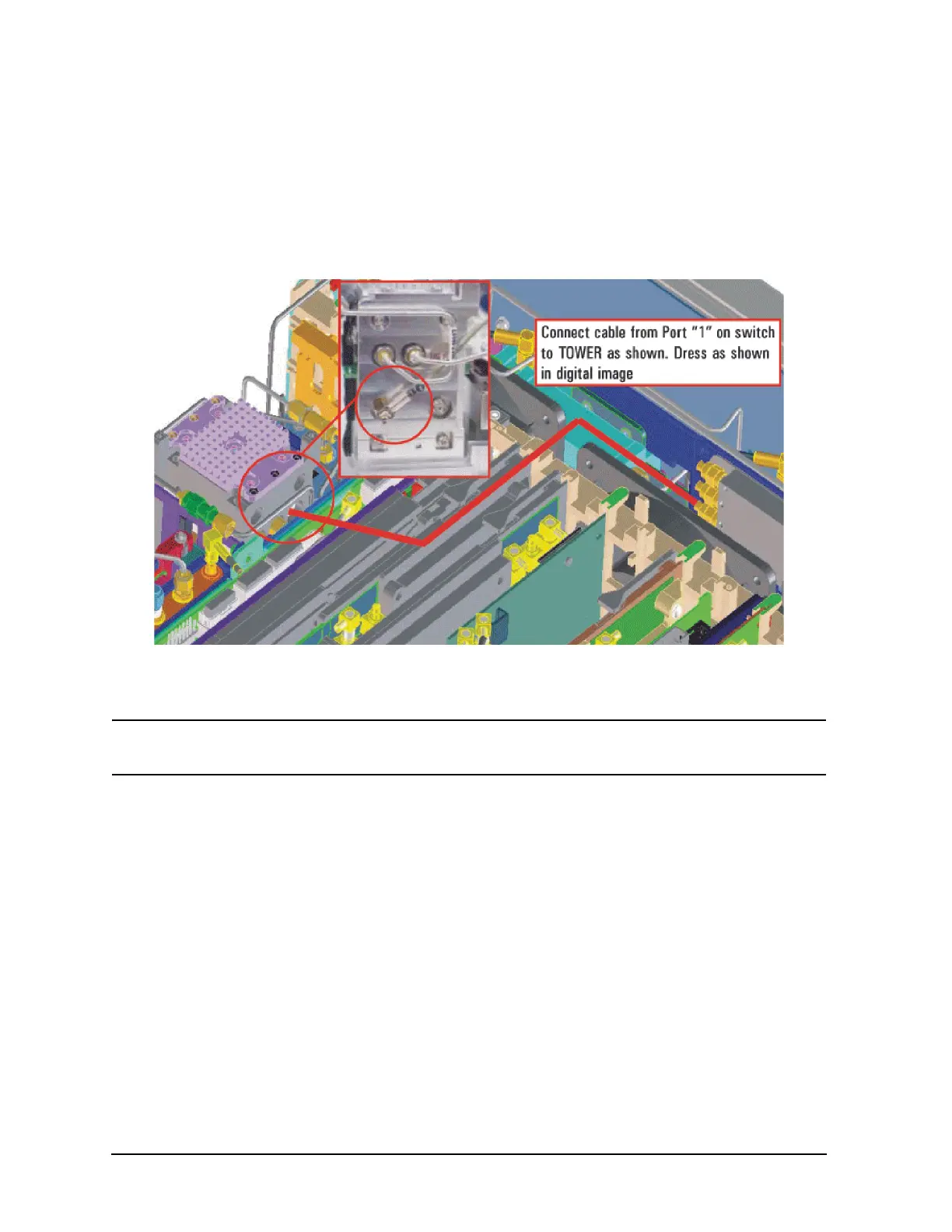
23.Refer to Figure 27. Locate cable W89, one end is already connected to Switch SW3
bottom port (Port 1). Route the cable next to the RF section sheet metal and directly
to the RYTHM as shown. Carefully align the SMB connector end of the cable with the
RYTHM connector by looking through the hole in the chassis. Press the SMB
connector on.
Figure 27 W89 Location
24.Reinstall the A13 Front End Driver, Synthesizer Assembly and the Reference
Assembly. Assure all cables are routed correctly.
NOTE The shrink-wrapped ferrite beads on the cable can be moved slightly to
aid cable routing.
25.Locate and remove cable W33 (Attenuator B to W34 on the RYTHM/SBTX). Discard
this cable, since it will be replaced by another cable. Refer to Figure 14.

 Loading...


