Air Techniques, Inc.
Page
12
Equipment Setup
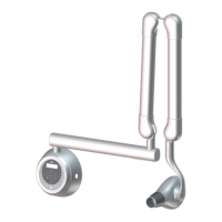
4.7 Support Load Requirements
The Provecta HD is designed to mount on either a single 4” x 4” wood stud or two 1½” x 3½” wood
studs that are spaced 16-inch on center and drywall or equivalent wall support.
The wall support and mounting hardware for the Provecta HD must withstand 220 pounds (99 kg)
shear load, and a withdrawal force of 1600 lbf (720 kgf). The wall fabrication and attachments to the
building structure must be capable of withstanding a moment load of 1353 lbf.ft (187 kgf.m).
4.8 Electrical Power Requirements
The system requires a three-wire power supply. The three-wires provide two power lines (L) Line and
(N) Neutral and a Ground.
4.9 Wiring Length and Gauge Requirements
Maximum length of wire and minimum gauge wire (AWG) from the power panel box to the Base Unit.
Line Voltage: 100 to 240 +/- 10%
Exposure Current: 8 Amp
Main Fuse Rating: 10 Amp
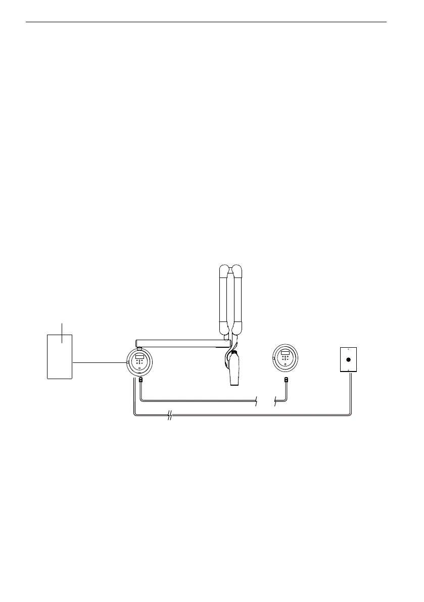
Provecta HD External Wiring Schematic
Control Unit with
Control Panel
Building
Power Panel
Box
Remote
Control
Panel
Remote Wallplate
Push Button
Exposure Switch
Note 2
Note 3
50 ft
(15 m)
Max
(RJ11 Connectors)
Note 1
Internal Wiring
(CAT 6 with RJ45 Connectors)
Note 1 - Power wiring
AWG 14 or higher as per local code requirements
Note 2 - Remote wiring
Recommended cable length for RJ45 is 50 feet (15m) maximum when using
Remote console and pushbutton exposure switch configurations.
No crossover in any of the RJ45 and RJ11 connector cables used for remote
console configuration (i.e,.1 to 1 connections).
Note 3 - Remote control options
See the six control configurations available for Provecta HD.