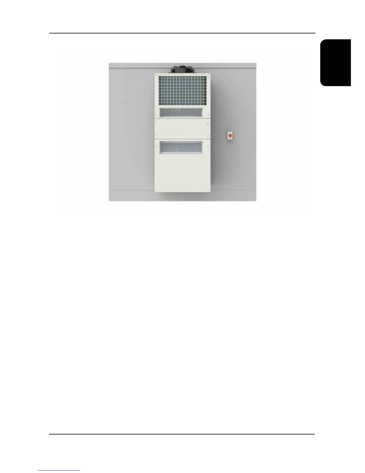
Mains Isolator
To comply with BS EN 6024-1:2006 Safety of Machinery – Electrical Equipment Machines, each unit shall have an
accompanying isolator (switch disconnecting device). The supply disconnecting device shall isolate the electrical
equipment of the telecoms unit from the electrical supply when required.
The isolator shall be easily accessible and mounted between 0.6m and 1.9m above the service level. An upper limit of
1.7m is recommended. The isolator part has been congured as a de-selectable component to allow the user the option
of supplying an isolator part of their choosing.
Compressor Soft Start
The electronic soft start enables the chiller compressor motor to be ramped to speed with the minimum full load current.
Further benets include removal of nuisance tripping, supply voltage dips and motor overheating.
DC Power Backup Supply
The new Ecotel range has been designed to include the option of connecting a -48VDC (2 wire positive earthed) backup
power supply. When this option is selected, DC evaporator fans are tted so that the controls circuit, evaporator fans
and free cooling damper can still operate from the DC supply allowing the unit to continue free cooling if there is a
power failure on the AC mains supply. The condenser fan, compressors and heaters require mains AC power to operate
therefore no other modes are available when running on the DC battery backup.
Phase Rotation/Phase Failure Relay
The phase sequence feature of the above option is available on all 3-phase units and is selected to ensure the correct
rotation of all AC motor type components. Permanent damage can occur if a compressor motor is run in the wrong
direction. The phase fail feature of the above option is available on all 1-phase and 3-phase units. When selected the
relay informs the unit controller of any loss of phases. The option of Phase Rotation/Phase Failure relay is a standard
feature with -48VDC congured units.
Electrical
Image shows typical isolator placement. For illustration purposes only.