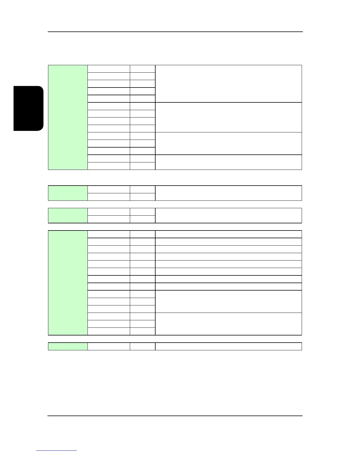
Installation Data
Interconnecting Wiring
Power Connections
Indoor Unit
L1
ç
Mains Incoming Supply
(400V / 3PH / + N / 50Hz or
380V / 3PH / + N / 60Hz)
L2
ç
L3
ç
N
ç
PE
ç
L1
ç
Mains Incoming Supply
(220V / 3PH / 60Hz)
L2
ç
L3
ç
PE
ç
L
ç
Mains Incoming Supply
(230V / 1PH / + N / 50Hz)
N
ç
PE
ç
-L
ç
Mains Incoming Supply
(-48VDC 2-wire positive earthed)
M
ç
Controls Connections
Standard
502 (802)
è
Auxiliary Alarm
524 (824)
ç
Option
502 (802)
è
Attend Mode / Remote On-Off
513 (813)
ç
Standard
560
ç
Non-Critical Alarm - Common
561
è
Non-Critical Alarm - N/O
562
è
Non-Critical Alarm - N/C
563
ç
Critical Alarm - Common
564
è
Critical Alarm - N/O
565
è
Critical Alarm - N/C
566
ç
Return Air Alarm - Common
567
è
Return Air Alarm - N/O
RX/TX-
ç
Network In (pLAN)
RX/TX+
ç
GND
ç
RX/TX-
è
Network Out (pLAN)
RX/TX+
è
GND
è
Option
BMS Interface
ç
BMS Interface
Note: - () Bracketed numbers refer to terminal numbers associated with the -48VDC emergency backup cooling option
pLAN Termination
The plugged termination ensures that the connections are made simultaneously. Failure to attach the cables this way
may cause damage to the controller.