Installation
● Check all services are present and accessible.
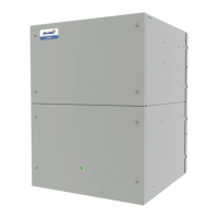
● Unpack the fan section and remove securing straps, leaving unit on its pallet.
● Using appropriate lifting equipment, lift the unit on its pallet and ease into position (local codes and regulations
should be observed).
● External xing: Once the unit is ush with the wall, secure with M10 plated bolts, with a washer on the interior and
exterior of the wall.
● The discharge air opening has a foam surround to provide a seal between the wall and the fan section. A bead of
sealant should be used to provide a air and water tight seal*.
● Seal evenly around the seam between the fan section and wall, achieving a water tight seal*.
● The ashing strip should be xed to the wall using screws (not provided). Seal to the wall and unit top using
silicon sealant to prevent moisture ingress*.
*Airedale recommend the use of Dow Corning 794 or equivalent.
● Where a cavity wall exists between the unit and wall, a wall sleeve will be required. (not supplied).
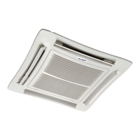
● Fix deection grilles to internal walls with tamperproof xings. Grille should come supplied with Moving Parts
Warning Label mechanically xed to grille ange.
Electrical
● A fused and isolated electrical supply of the appropriate phase, frequency and voltage should be installed.
● Each unit requires an independently fused and isolated power supply.
● Install the remote room sensor in an appropriate position and run the interconnecting wire back to the unit control
panel, refer to Interconnecting Wiring.
● Install mains supply refer to Interconnecting Wiring (and optional -48VDC. NOTE: – Connect the poles correctly).
● Pass through the set holes located on the back of the fan section, feed through the into the electrical control panel
● Route via trunking and terminate in supplied terminals, refer to supplied wiring diagram.
Installation Data
Lifting/Positioning
● Remove packing and check that the unit is exactly as ordered. Any discrepancy to order, or transit damage,
should be reported to Airedale immediately.
● Airedale recommends that whenever possible, the packaging is left covering the unit, to protect it from damage
and general site debris.
● Care should be taken during handling and lifting, that the unit is well supported and properly balanced.
● Care should be taken that there are no obstructions to free airow, particularly in the vicinity of the condenser fan
discharge (outdoor) (minimum of 600mm is required) and also the return/discharge air (indoor).
Airedale will accept no responsibility for mishandling during the positioning of the equipment.