29
7.4. Filter Change
All lters in the air handling unit (incl. cooling module) are
monitored by the unit’s lter monitoring system. The lters
must be replaced when the monitoring system indicates a
lter change, but at least annually. Filter monitoring can be
adapted to local conditions using Airlinq Service Tool. The
lters are tested automatically daily (time can be set using
“Airlinq Service Tool”).
NB! Used lters must be disposed of according to
their contamination with particles (waste code 1502),
atmospheric particles (waste code 150203) or ‘hazard-
ous’ substances (waste code 150202).
NB! When changing the lter, we recommend using
appropriate safety equipment such as safety goggles,
disposable gloves and a dust mask. Used lters must
immediately be disposed of in a dustproof bag after
they have been removed from the unit.
NB! The control system lter monitoring must be reset
after a lter change.
7.4.1. Reset Service
Airlinq Viva:
Reset lter change alarm by pressing and holding the holiday
mode button and function button simultaneously for 10
seconds. The unit will then automatically start, the control
panel will ash a short amber warning symbol followed by
a short red alarm symbol.
Airlinq Orbit:
Reset the lter alarm under control panel menu “Settings
- Reset Service” or using a PC running Airlinq Service Tool.
>> Press “Conrm” to reset service or “Cancel” to cancel
the reset.
Units with no control panel:
The lter change alarm must be reset using a PC running
Airlinq User Tool or Airlinq Service Tool.
7.4.2. Cooling Module Filter Change
NB! When changing lters, the unit must be switched
o (press function button for at least 2 seconds),
disconnected from the mains and prevented from
being switched on.
• Carefully open the base plate while it is supported.
NB! Open the side of the wall frame rst. The base
plate is heavy.
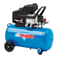
•
Slacken the retaining plate (certain models only)
and pull out the old lter on the fresh air side of
the frame.
•
Clean the inside of the cooling module and supply air
duct, check component condition and cleanliness.
Clean the components if necessary.
•
Insert a new lter with the correct direction of ow in
the lter frame. The arrow on the side of new lters
(M5, F7, F9) shows ow direction. The arrow must
point into the unit. Fit the retaining plate (certain
models only).
• Close the base plate, lock covers.
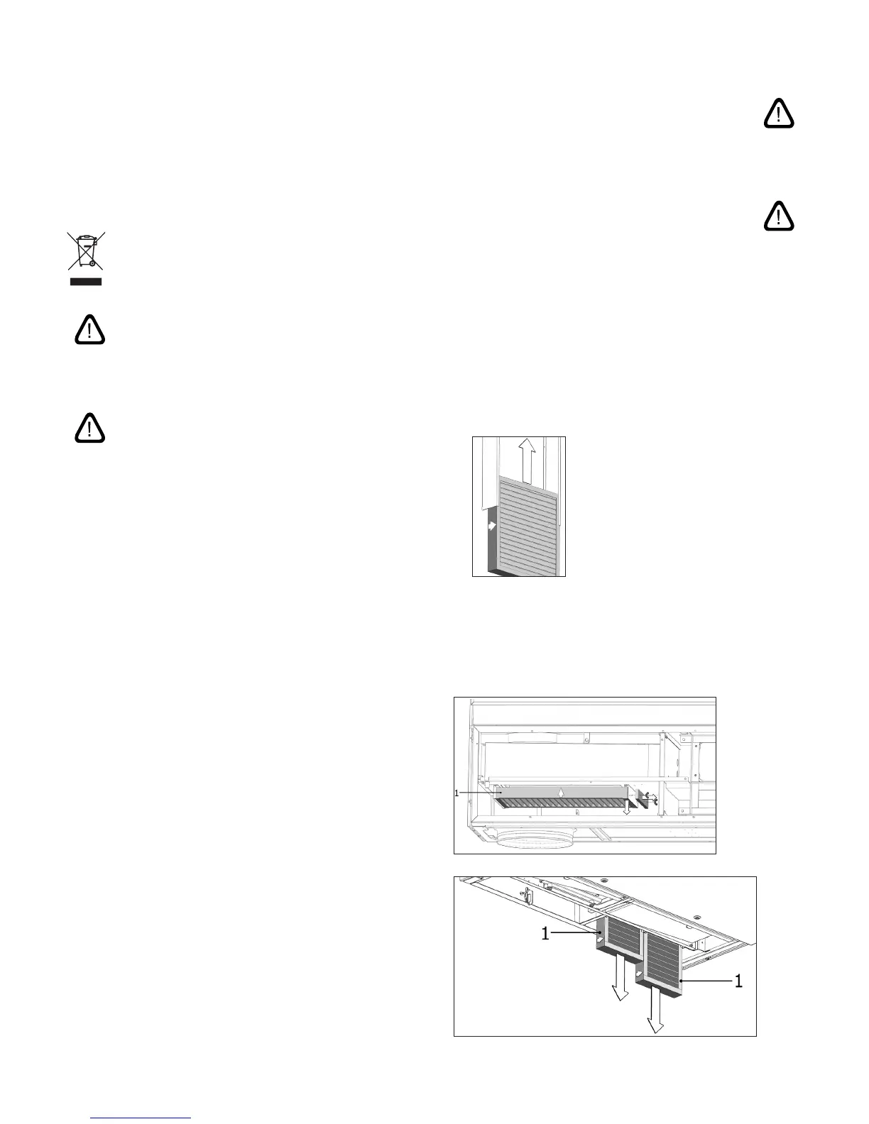
•
Replace the exhaust air lter on the air handling
unit. See sect. “Filter Change for CV 80-200, DV
1000, AM 100, 300, 500, 800, 1000” on page 29
Filter position:
or
 Loading...