22
Bad compression
• Restriction air filter/cleaner or induction system.
• Incorrect valve tip clearances.
• Faulty piston rings.
The engine starts and stops
• Dirty fuel filter element.
• Restriction air filter/cleaner or induction system.
• Air in fuel system.
• Bad connection towards oil pressure switch/coolant
temperature switch.
Note: Please, look the engine manual for maintenance.
11. ALTERNATOR DESCRIPTION
11.1. General
The alternator fitted on the generator set is of the
brushless self-excitation type which eliminates the
maintenance associated with slip rings and brushes.
The control system, consist of an automatic voltage
regulator, protective circuits.
11.2. Construction and Components
The stator core is produced from insulated low loss
electrical grade sheet steel laminations. These are built
and welded under a fixed pressure to give an extreme
-
ly rigid core to withstand vibration and load impulses.
The complete wound stator is, after impregnation,
pressed into the frame and pinned into position.
The rotor assembly, which comprises the alternator
rotating field systems, the exciter rotating diode system
and the cooling fan. The complete rotor assembly is
dynamically balanced to ensure vibration-free running.
At the drive end of the rotor assembly a cast-alumi
-
num centrifugal fan draws cooling air through screened
covers at the non drive end and discharges it through
similar side mounted covers at the drive end.
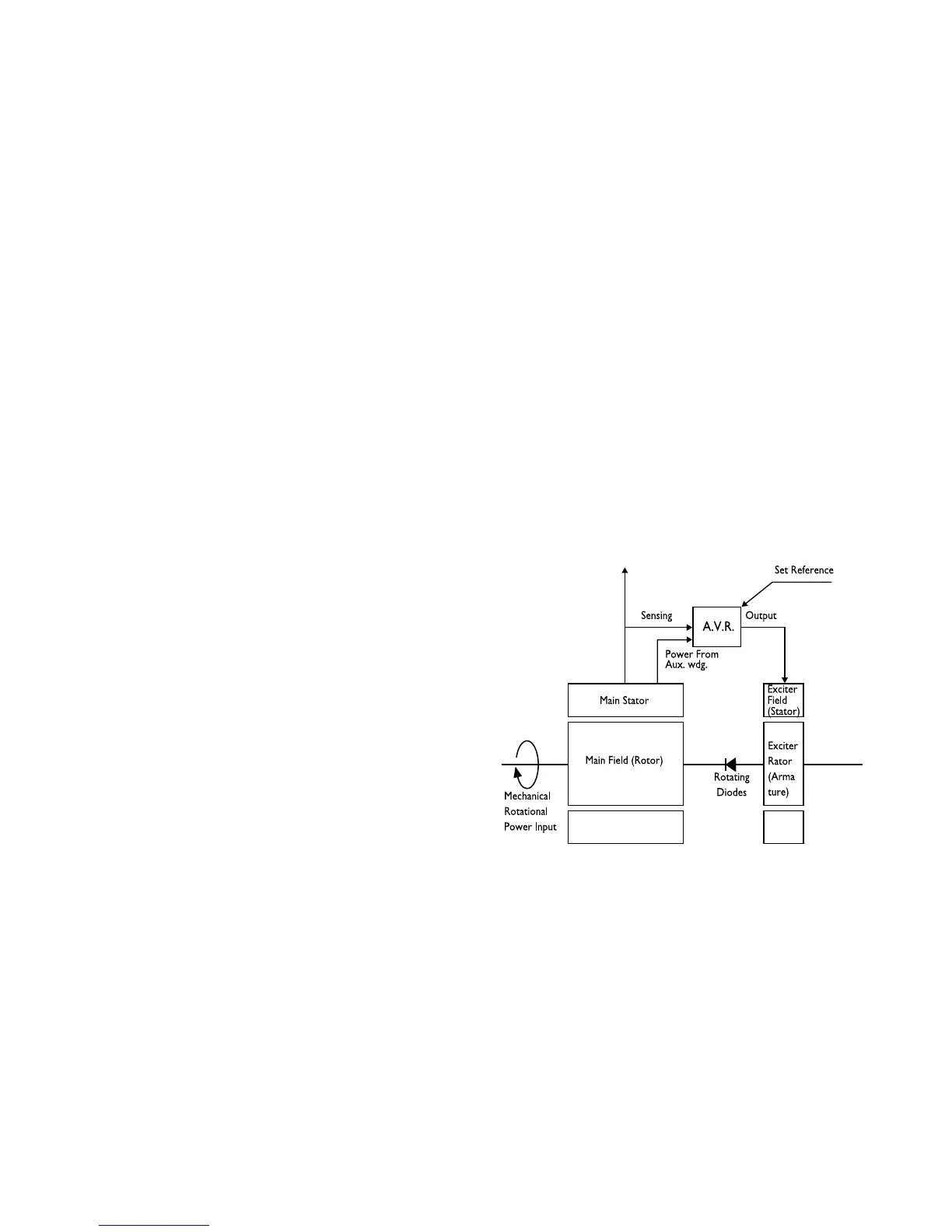
11.3. Operation
The electrical power produced by the generating set is
derived from a closed loop system consisting principal
-
ly of the exciter rotor the main revolving field and the
automatic voltage regulator (see Figure 11.1)
The process begins when the engine starts to rotate
the internal components of the alternator. The residual
magnetism in the main rotor produces a small alter
-
nating voltage (AC) in the main stator. The automatic
voltage regulator rectifies this voltage (converts it to
DC) and applies it to the exciter stator.
This DC current to the exciter stator creates a mag
-
netic field which in turn, induces an AC voltage in the
exciter rotor. This AC voltage is converted back to DC
by the rotating diodes.
When this DC voltage appears at the main rotor, a
stronger magnetic field than the original residual field
is created which induces a higher voltage in the main
stator. This higher voltage circulates through the sys
-
tem inducing an even higher DC voltage back at the
main rotor. This cycle continuous to build up the volt
-
age unit it approaches the proper output level of the
generating set. At this point the automatic voltage reg
-
ulator begins to limit the voltage being passed to the
exciter stator which, in turn, limits the overall power
output of the alternator.
This build-up process takes place in less than one sec
-
ond.
Figure.11.1. Meccalte alternator, operating principles
block schematic diagram
11.4. Automatic Voltage Regulator
The Automatic Voltage Regulator (AVR) maintains a
no load to full load steady state voltage to tight toler
-
ances. The AVR has a volt/hertz characteristic which
proportionally reduces the regulated voltage at re
-
duced speeds.