7
are liable to cause serious trouble to persons or mate-
rial or financial damage (i.e. in hospitals, industrial plants
with non-stop operating cycles, etc) or to meet peak
energy demands.
According to their application, the sets are further di
-
vided into:
- Set for use on land.
- Set for use at sea.
The sets for use on land can be either:
- Stationary sets (fixed installation), or
- Mobile sets (mobile installation)
These two types of sets are available in a vast range
of versions, for every operating requirement, the main
ones being:
01. Hand control generating sets
02. Stand-by generating sets
The standard stationary generating set comprises:
• Diesel engine.
• Synchronous generator.
• Coupling.
• Radiator.
• Metal sub-base with vibration isolators.
• Starter batteries.
• Fuel tank within the baseframe.
• External fuel tank (for high power generators).
• Instrument panel.
• Exhaust gas silencer.
Aksa Generator Set has been designed as a complete
package to provide superior performance and reliabil
-
ity.
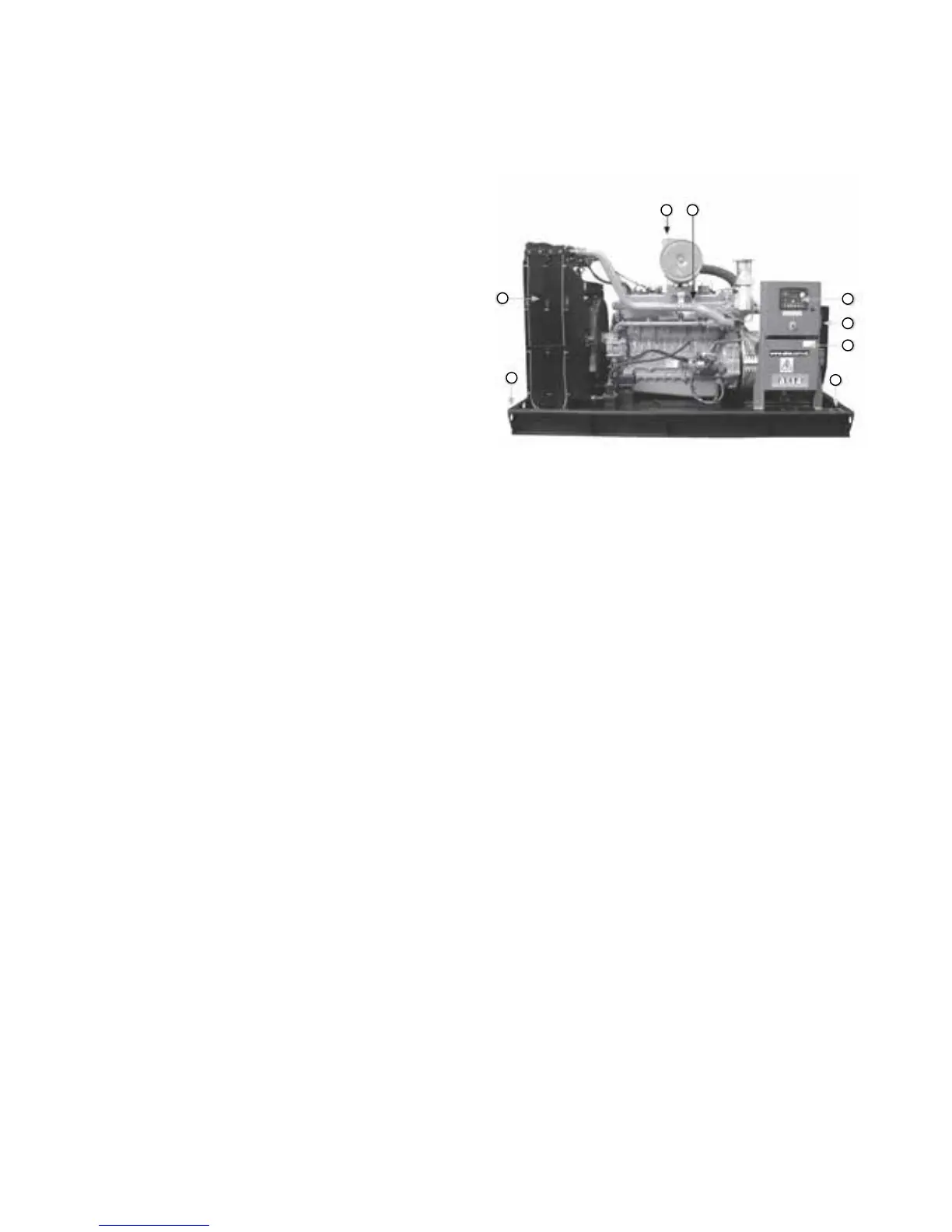
Figure 3.1. Identifies the major components. This figure
is of a typical generating set. However, every set will
be slightly different due to the size and configuration of
the major components. This section briefly describes
the parts of the generating set. Further information is
provided in later sections of this manual.
Aksa generating sets are an Alternating Current gen
-
erator, built for continuous running at sites where no
electricity is available (some models are excepted) or
as stand-by in case of interruption of the mains.
The generator operates at 230/220 V in line-to-neutral
mode and 400/440 V in line-to-line mode. at 50 Hz ,
120V/208, 220/380, 277/480 at 60 Hz. Some diesel
engines couldn’t be used as 60 Hz.
Water cooled diesel engines which are produced by
Perkins, are used in AKSA generator Sets
3.2. Generating Set Main Parts
Figure 3.1. Typical generator set configuration
No Description
1. Generator set rating label.
2. Diesel engine.
3. Air filter.
4. Radiator.
5. Alternator.
6. Terminal box.
7. Base frame.
8. Control Panel.
3.3. Diesel Engine
The diesel engine powering the generator set (Item 2)
has been chosen for its reliability and the fact that it
has been specifically designed for powering generator
sets. The engine is of the heavy duty industrial type
with 4 stroke compression ignition and is fitted with all
accessories to provide a reliable power supply. These
accessories include, among others, a cartridge type dry
air filter (item 3) and a mechanical or an electronic
engine speed governor.
The engine cylinder block is cast in one piece cast iron,
vertical cylinders inline overhead valves and camshaft
in block. The cylinder heat is made of special cast iron.
The thermally loaded flame plate is efficiently water
cooled. The crankshaft is forged in one piece in high
tensile steel.
Lubrication: forced lubrication via gear pump, special
Spin-on filters, lubricant cooling via heat exchanger.
3 2
8
5
6
1
7
4