8
3.4. Engine Electrical System
The engine electrical system is 12 volt or 24 volts DC,
negative ground/earth. This system includes an electric
engine starter, a battery and a battery charging alterna
-
tor. For 12 volts electrical system one battery is given.
For 24 volt system two lead-acid batteries are given.
Other types of batteries may be fitted if they were
specified. Batteries are detailed in Section 4.
3.5. Cooling System
The engine cooling system is water cooled. The water
cooled system is comprised of a radiator (item 4) a
pusher fan and thermostat. The alternator has its own
internal fan to cool the alternator components.
3.6. Synchronous Alternator
Horizontal axle alternator (synchronous three phase),
on rolling bearings, self-ventilated within the room with
low-loss silicon-sheet stator bundle, electrolytic copper
winding with class H insulation.
Case –type damper winding for parallel operation (on
high-powered alternators).
The output electrical power is normally produced by
IP23 and a screen protected and drip-proof, self-excit
-
ing, self regulating, brushless alternator. (Item 5) Fine
tuned to the output of this generating set. Mounted
on top of the alternator is a sheet steel terminal box
(item 6)
3.7. Coupling
If Single bearing alternators are used, a special flexible
disk is used in place of a flexible coupling. If two bear
-
ing alternator is used, Engine and alternator are firmly
joined by a coupling cone that guarantees the proper
assembly coaxiality.
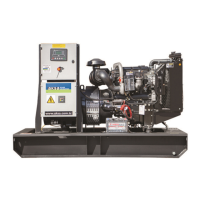
3.8. Fuel tank and Base frame
The engine and alternator are coupled together and
mounted on a heavy duty steel base-frame (Item 7).
This base frame includes a fuel tank with capacity of
approximately 8 hours operation under variable loads.
The tank is complete with filling cap and fuel level
gauge and is connected by flexible joints to the intake
piping and to the overflow piping containing fuel from
the injector drain. High power Gensets fuel tank is sep
-
arate from set.
3.9. Vibration Isolation
The generator set is fitted with vibration isolators
which are designed to reduce engine vibration being
transmitted to the foundation on which the generator
set is mounted. These isolators are fitted between the
engine /alternator feet and the base frame.
3.10. Silencer and Exhaust system
An exhaust silencer is provided loose for installation
with the generating set (for open sets). The silencer
and exhaust system reduce the noise emission from
the engine and can direct exhaust system reduce the
noise emission from engine and can direct exhaust gas
-
es to safe outlets.
3.11. Control System
One of several types of control systems and panels
(item 8) may be fitted to control the operation and
output of the set and to protect the set from pos
-
sible malfunctions. Section 6 of this manual provides
detailed information on these systems and will aid in
identification of the control system fitted on the gen
-
erator set.
4. ELECTRIC STARTING SYSTEMS
Electric starting systems are generally used on all
gen-sets. Electrical starting system consists of a start
-
er, mounting flange to the flywheel and bendix gear.
There could be 2 starters on big engines.
The power source for electric starting systems is a 12V
or 24V DC battery system. The starting voltage is de
-
termined by engine size, 24 VDC being used for larger
engines to reduce starting current and hence cable
size. Control of starting is via a start solenoid which is
controlled by the gen-set control system.
4.1. Battery Systems
Batteries are of two types– lead acid and NiCad. Lead
acid batteries are generally used, being the least ex
-
pensive. NiCad batteries are used where longer life,
etc., is required.
Batteries are one of the main parts of the Gensets, and
it could be said that 90% of the Gensets fault is caused
by battery. So it is important to do regular mainte
-
nance and checks on batteries. Batteries are mounted