843
C - Opti-Box
[1] Connection for the speed stop limit switch
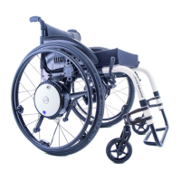
A speed stop limit switch provides the option of regulating the speed depending on the
switch position. Wheelchairs with stand-up and lift function can, for example, reduce the
speed of these two positions, or block travel. When you first insert the speed stop limit
switch the speed is reduced to 50% of the maximum speed. When the switch is closed,
the e-fix continues to travel at maximum speed. The reduced speed can be modified by
your specialist dealer.
[2] Connection for an external on/off switch
Option of switching the e-fix on or off using an external button.
[3] Plug for connecting external control systems
This enables the e-fix to communicate with external control systems.
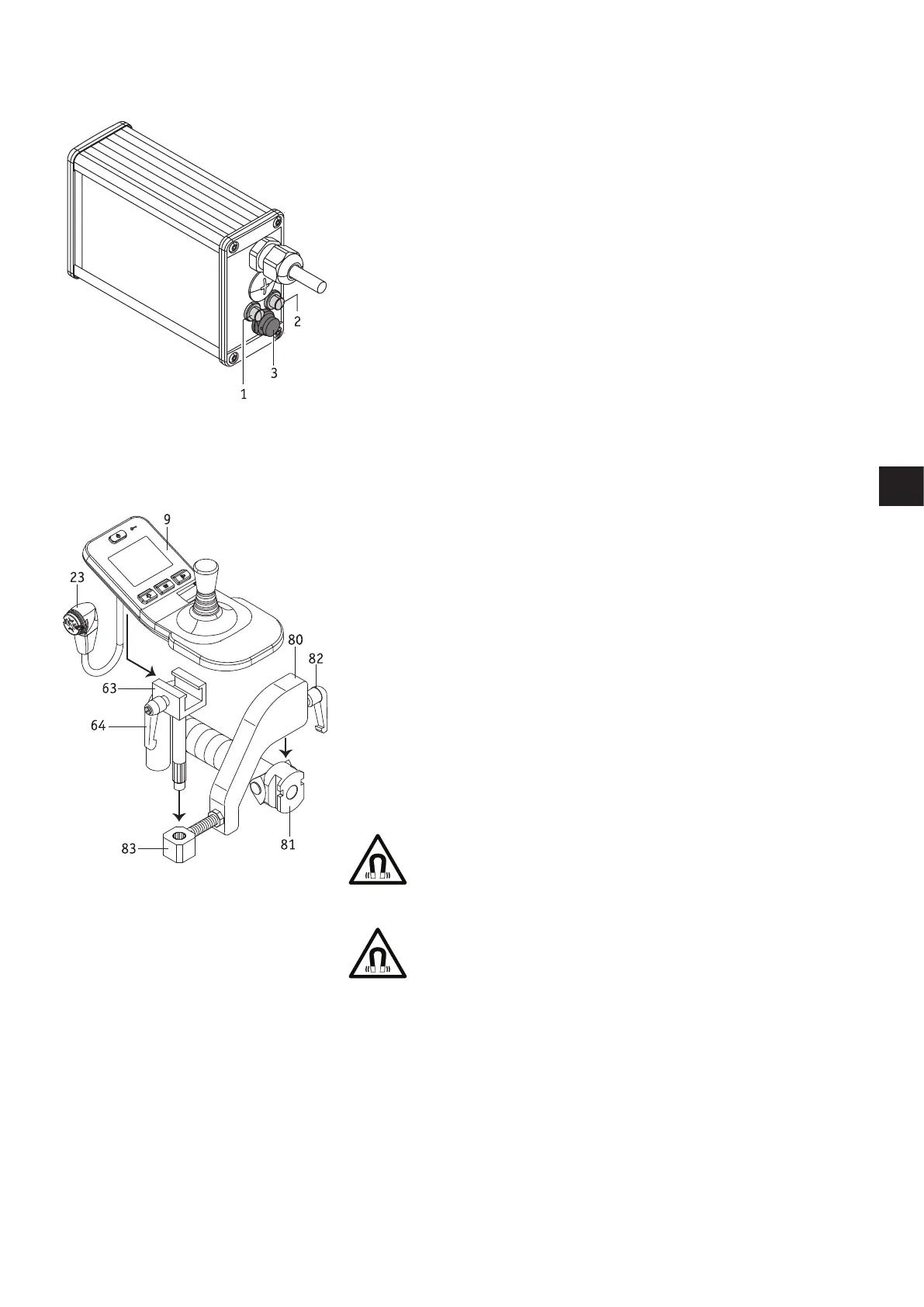
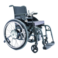
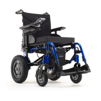
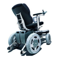
D - Attendant control unit
The e-fix can be operated by the wheelchair user themselves and by an attendant. This
just requires the control unit to be installed in a holder attached to the wheelchair
handle. This is not included in the standard scope of delivery but can be fitted sub-
sequently by your specialist dealer at any time.
If an attendant should control the e-fix, proceed as follows:
• Switch off the e-fix.
• Remove the control unit (see chapter 5.1).
• Push the holder bracket [80] into the attachment [81] fitted to the wheelchair handle.
• Secure the holder bracket [80] with the locking lever [82] in the attachment [81].
• Push the sliding part [63] into the holder [83].
• Slide the control unit [9] into the sliding part [63] and secure it using the locking
lever [64].
• Connect the control unit [9] to the battery (see chapter 5.1).
• If the control unit needs to be used directly by the wheelchair user, dismantle it by
following the above steps in reverse order.
Before inserting the plug [23] into the socket [29] of the battery
pack, ensure that both parts are clean and there are no metallic
particles on them. If you detect such particles, use a dry and clean
cloth to remove them.
The control unit plug [23] is magnetic. Therefore prevent the plug
coming into contact with medical implants, electronic storage
media, bank cards or similar items.