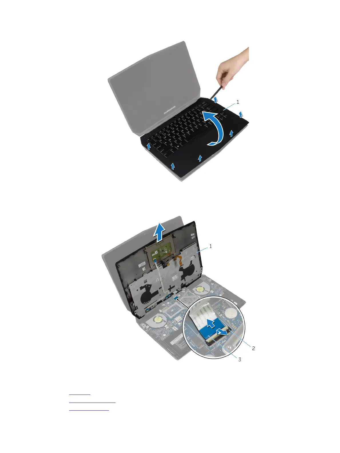
6 Gently lift the palm-rest assembly and turn it over.
1 palm-rest assembly
7 Lift the connector latch and disconnect the power-button board cable from the system board.
8 Lift the palm-rest assembly o the computer base.
1 palm-rest assembly 2 connector latch
3 power-button board cable
9 Remove the keyboard.
10 Remove the power-button board.
11 Remove the status-light board.
25