17. Rear-chassis fan connector (FAN SYS1) 18. Rear-chassis fan LED connector (LED FAN SYS1)
19. Liquid cooling pump fan connector (FAN PUMP) 20.Liquid-cooling pump LED connector
21. Power-supply connector (ATX3) 22.Top-chassis fan connector one (FAN_SYS4)
23. Power-supply connector (ATX2) 24.CPU socket
25.Top-chassis fan connector two (FAN_SYS5) 26.Memory-module slot, DIMM1
27. Memory-module slot, DIMM2 28.SATA power connector (SATA PWR)
29.Side-light connector (SIDE LIGHT)
Recommended tools
The procedures in this document may require the following tools:
● Philips screwdriver #1
● Flat-head screwdriver
● Plastic scribe
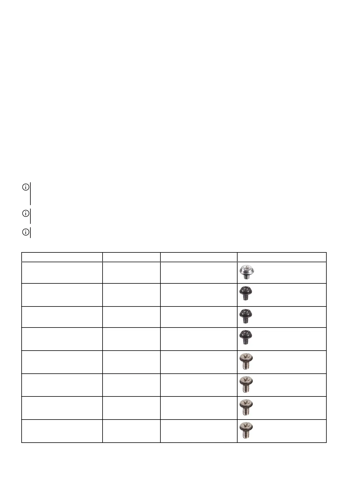
Screw list
NOTE: When removing screws from a component, it is recommended to note the screw type, the quantity of screws, and then
place them in a screw storage box. This is to ensure that the correct number of screws and correct screw type is restored when
the component is replaced.
NOTE: Some computers have magnetic surfaces. Ensure that the screws are not left attached to such surfaces when replacing a
component.
NOTE: Screw color may vary with the configuration ordered.
Table 1. Screw list
Component Screw type Quantity Screw image
Power-supply unit bracket #6-32x1/4" 2
Power-supply unit bracket (for
computers shipped with clear
left-side cover)
#6-32x1/4" 2
Power-supply unit #6-32x1/4" 4
Power-supply unit (for
computers shipped with clear
left-side cover)
#6-32x1/4" 4
Side light (for computers shipped
with clear left-side cover)
M3x5 2
Radiator and fan assembly for
liquid cooler
M3x5 2
Rear-chassis fan M3x5 1
Lower front-chassis fan M3x5 1
13