21. Power-supply connector (ATX3) 22.Top-chassis fan connector one (FAN_SYS4)
23. Power-supply connector (ATX2) 24.CPU socket
25.Top-chassis fan connector two (FAN_SYS5) 26.Memory-module slot, DIMM1
27. Memory-module slot, DIMM2 28.SATA power connector (SATA PWR)
29.Side-light connector (SIDE LIGHT)
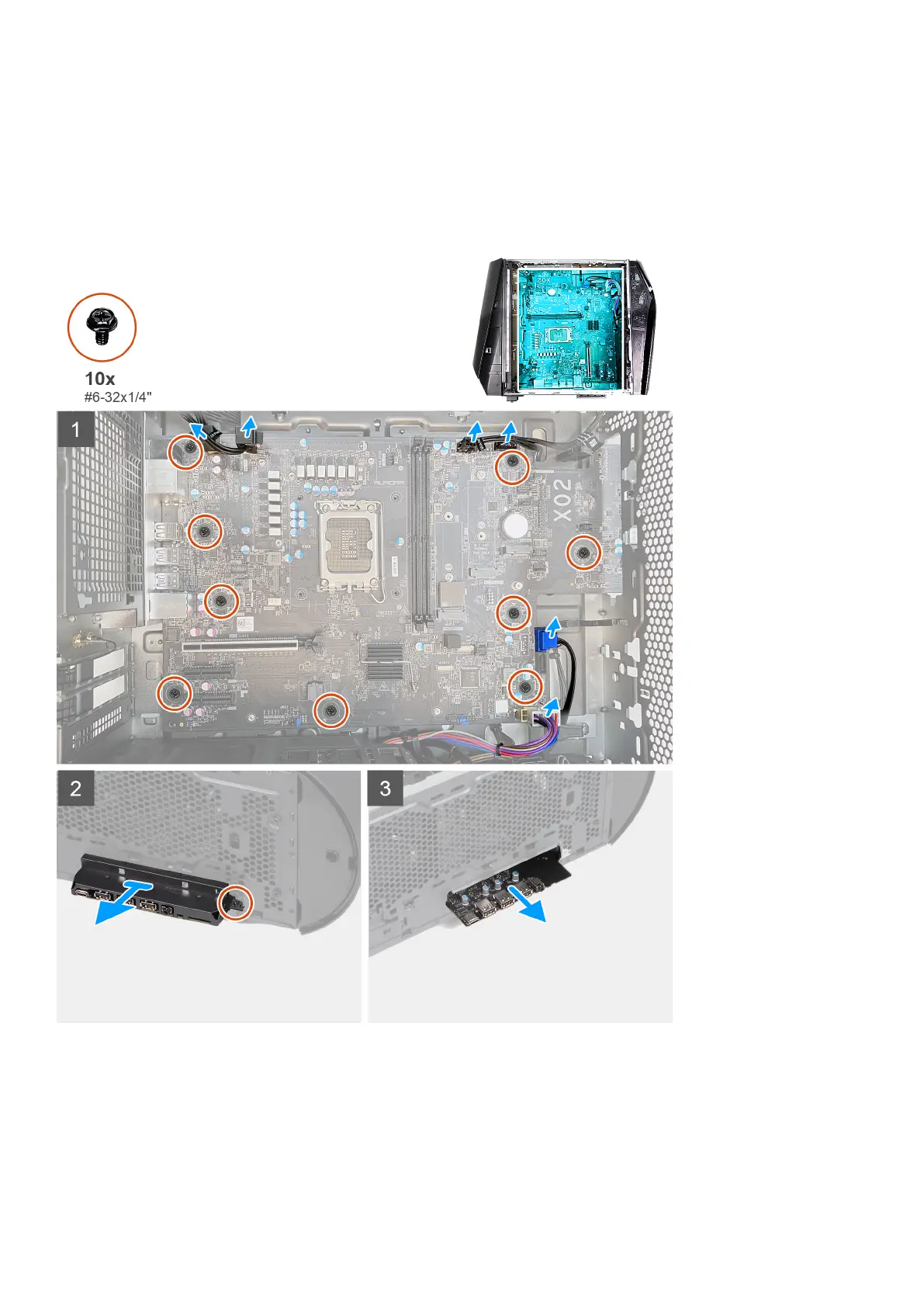
The following images indicate the location of the system board and provide a visual representation of the removal procedure.
84