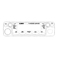
16 32
8 9
10 14131211
7
5
15
4
•Primary Functions
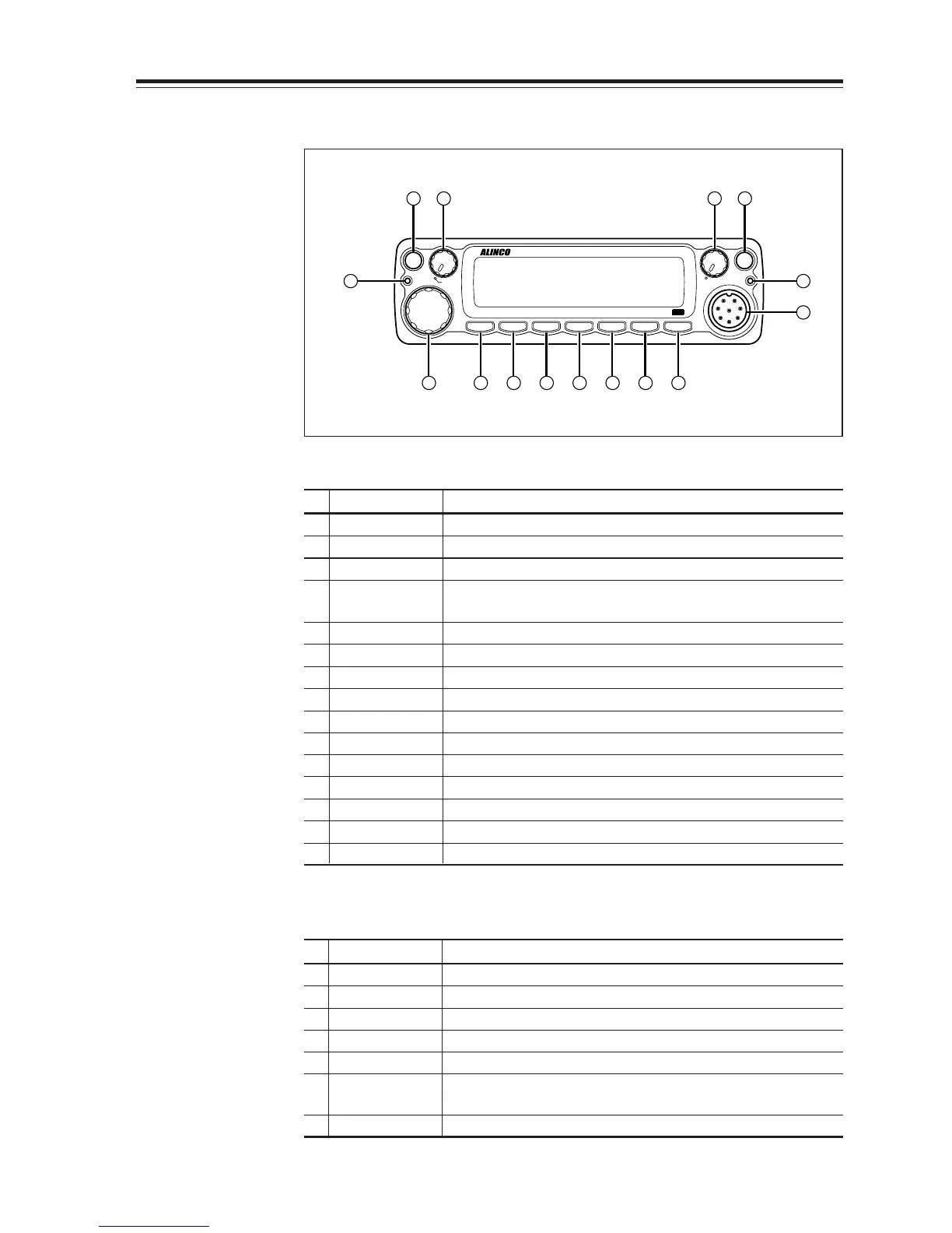
No.
Key Function
1 PWR key Power turns ON/OFF whenever switch is pressed.
2
Main VOL knob
Adjusts the volume level on the MAIN band.
3
Sub VOL knob
Adjusts the volume level on the SUB band.
4 Main TX/RX During transmission on the MAIN band, illuminates in
indicator Red, and during reception illuminates in Green.
5 Sub RX lamp During reception on the SUB, illuminates in Green.
6 V/M/MW Switches between VFO mode and memory mode.
7 Dial
Changes the frequency, memory channel and various settings.
8 BAND/VVUU Switches the MAIN band to VHF or UHF.
9
CALL/RX BAND
Switches to CALL Mode.
10 MHZ/SHIFT In VFO mode, changes frequency in 1 MHz steps.
11
TSDCS/LOCK
Sets the tone squelch and DCS setting.
12 HL/ PACKET Switches HI/MID/LOW of transmission power.
13 SQL/DIGITAL Sets the squelch level.
14 FUNC/SET Sets functions.
15
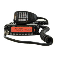
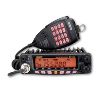
Mic. Connector
Connection for the provided microphone.
•
Functions which can be activated while [F] appears, after pressing the FUNC Key
No.
Key Function
6 V/M/MW Write a to memory channel.
8
BAND/VVUU
Switches to VV/UU mode.
9
CALL/RXBAND
Switches reception bands.
10 MHZ/SHIFT Sets the shift direction and the offset frequency.
11
TSDCS/LOCK
Sets the key lock function.
12 HL/PACKET Accesses the packet communication mode or the
geolocating communication mode.
13
SQL/DIGITAL
Accesses the digital voice communication mode.
* [F] illuminates when the FUNC key is pressed.