12
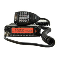
Part Names and Functions
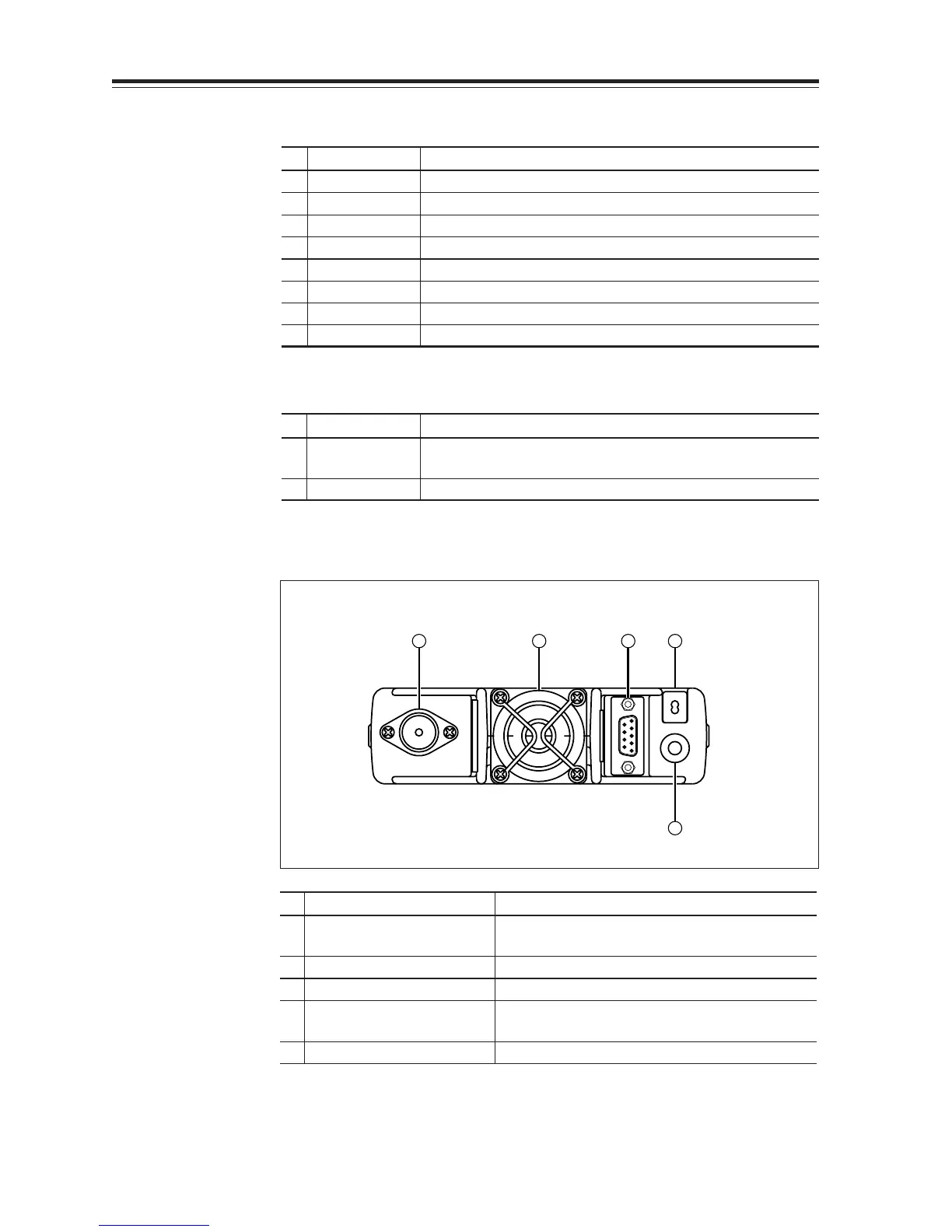
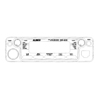
Rear Panel
4 3 5 2
1
No.
Key Function
1
External Speaker Terminal
Terminal for optional external speaker.
(Also used for the clone function.)
2 Power cable Connects to the 13.8VDC power supply.
3 Air-cooling fan
Cools the unit during transmission. (PTT activation)
4 Antenna Connector Connect an antenna with 50 ohm impedance.
(PL-259 or compatible)
5
D-SUB Connector (Optional)
Connects to a personal computer for packet use.
•
Functions that can be activated while pressing the FUNC Key
No.
Key Function
1 PWR Reset to factory default settings.
5 V/M/MW Erase the memory.
8 BAND/VVUU Switches to the single band mode.
9
CALL/RXBAND
Accesses the clone function mode.
10 MHZ/SHIFT Switches to wide/narrow mode reception.
11
TSDCS/LOCK
Switches to the AM reception mode.
12 HL/PACKET Sets the channel name function.
13 SQL/D Accesses the power supply voltage indication mode.
• Functions that require continuous pressing to be activated.
No.
Key Function
13 SQL/DIGITAL When pressed for 1 second, the monitor function is on.
(When the shift is set, the reverse function is on.)
14 FUNC/SET When pressed for 2 seconds, accesses the set mode.