13
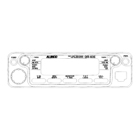
Part Names of Functions
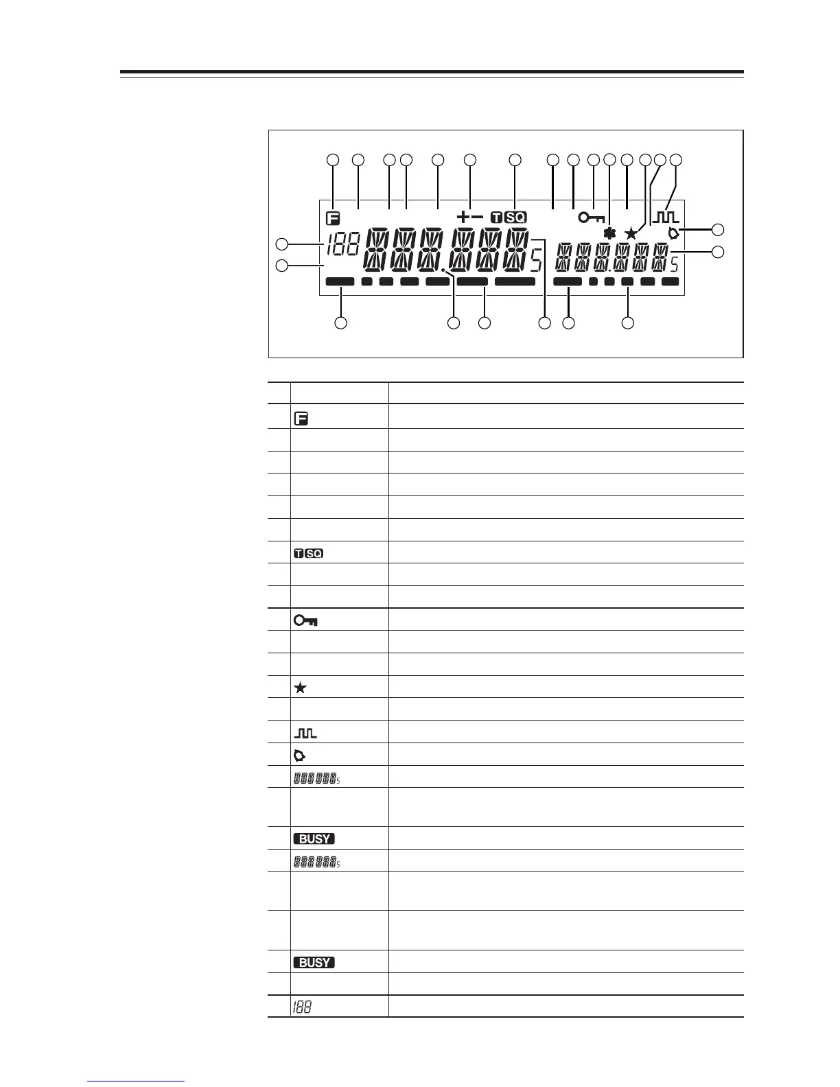
Display
DCS
SUB
TNC
R
AM
SQL
BUSY BUSY1 3 5 7 9
MiLo
Nar
2 3 4 5 6 7 8 9
10
11
12 13 14 15
1
23 22 21 20 19 18
16
17
24
25
No.
Key Function
1 Appears when FUNC Key is pressed.
2AM Appears during AM reception.
3Mi Appears when transmission power is set to MID.
4Lo Appears when transmission power is set to LOW.
5 Nar Appears when in narrow band reception mode.
6 +/- Appears when setting the shift.
7 Appears when setting the tone squelch.
8 DCS Appears when setting the DCS.
9 SUB Appears when SUB band is on the MAIN side.*
10 Appears when setting the key lock.
11 * Appears when setting the theft alarm function.
12 TNC
Appears when in packet mode (Optional EJ-50U required).
13
Appears when SUB band is in the memory mode or call mode.
14 R Appears when the reverse function is activated.
15 Appears when in the digital voice communication mode.**
16 Appears when setting the bell (pager) function.
17 Indicates the frequency or memory name on the SUB side
18 S Meter Indicates the relative signal strength level of transmission/
reception on the SUB side.
19 Appears when a signal is being received on the SUB side.
20 Indicates the frequency or memory name on the MAIN side.
21 S Meter Indicates the relative signal strength level of transmission/
reception on the MAIN side.
22
.Decimal point
Appears when changing the DCS decode settings.
Disappears when setting Memory Channel skip.
23 Appears when a signal is being received on the MAIN side.
24 SQL Appears when setting the squelch level.
25 Indicates memory numbers in the memory mode.
*SUB band is the band exclusive for reception when in V-V/U-U.
** T version only. Optional EJ-47U required.