4
2
Initial Installation
▼
Before connecting the DC power to the transceiver, be sure to
switch the transceiver and the DC power supply OFF.
▼
Do not plug the DC power supply into an AC outlet until you make
all connections.
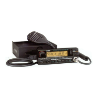
Fixed Station Operation
In order to use this transceiver for xed station operation, you will need
a separate 13.8V DC power supply (not included) , Please contact local
dealer to require.
The current capacity of your power supply must be 20A or more.
Connect the DC power cable to the regulated DC power supply
and ensure that the polarities are correct. (Red: positive, Black:
negative).
▼
Never directly connect the transceiver to an AC outlet.
▼
Use the supplied DC power cable to connect the transceiver to a
regulated power supply.
▼
Do not substitute a cable with smaller gauge wires.
Regulated
power supply
Red
Black
DC power cable with fuse holder
REPLACING FUSES
If the fuse blows, determine the cause, then correct the problem. After the
problem is resolved, replace the fuse. If newly installed fuses continue to
blow, disconnect the power cable and contact your dealer for assistance
.
Only use fuses of the specied type and rating, otherwise the transceiver
could be damaged.
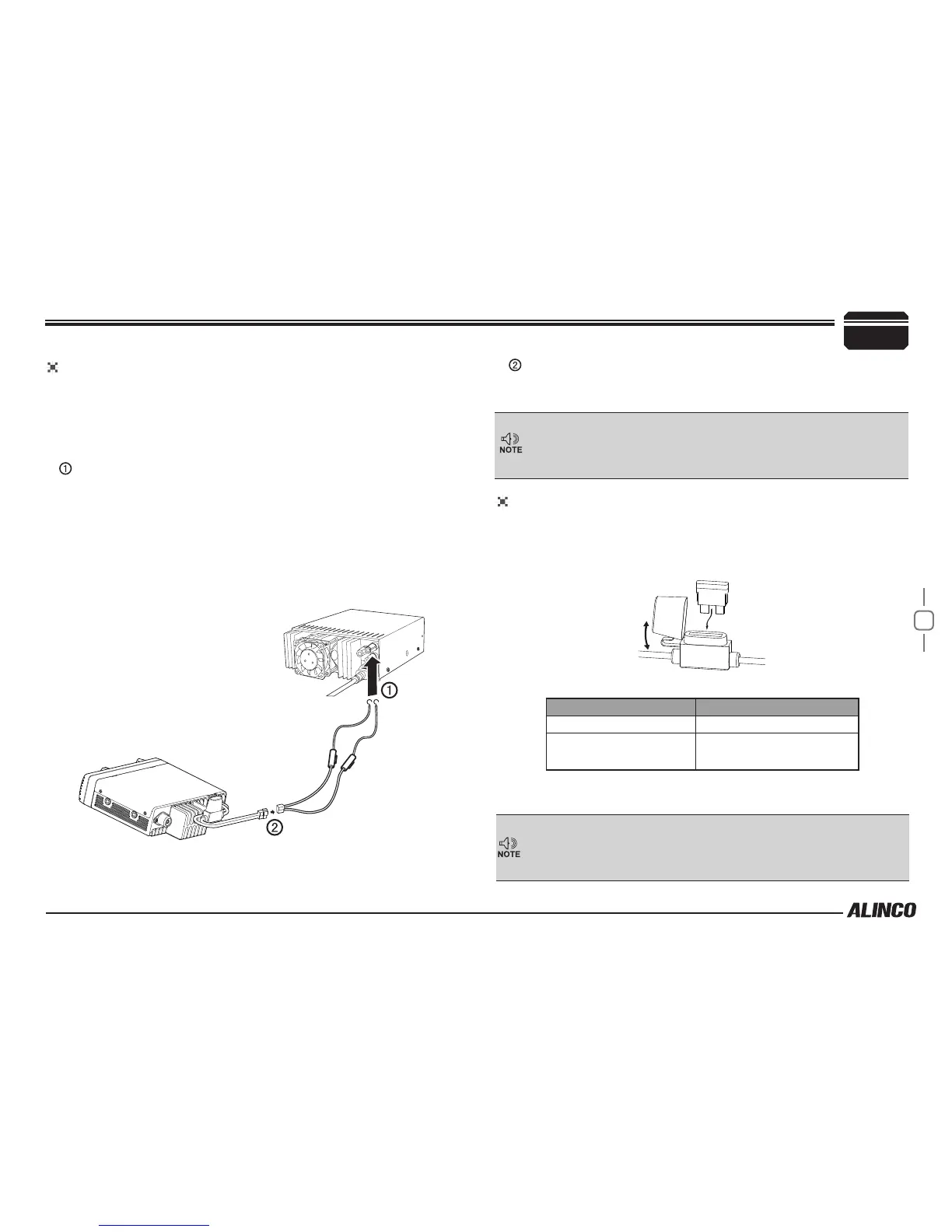
Fuse Location Fuse Current Rating
Transceiver 20A
Supplied Accessory DC
power cable
20A
If you use the transceiver for a long period when the vehicle battery is
not fully charged, or when the engine is OFF, the battery may become
discharged, and will not have sufcient reserves to start the vehicle. Avoid
using the transceiver in these conditions.
Connect the transceiver’s DC power connector to the connector on
the DC power cable.
▼
Press the connectors rmly together until the locking tab clicks.