Part 3.9: Keys and LED Light
The AXKU15 base board has seven LEDs, one power indicator, two serial communication indicators, and four user
LEDs. When the development board is powered on, the power indicator will light up; the four LEDs are connected
to the IO of the FPGA, and the user can control the on and off through the program. When the IO voltage
connected to the user LED is high, the user LED will light up, and when the IO voltage is low, the user LED will be
off. In addition, there are four user keys on the board. The default key signal is high. When the key is pressed, the
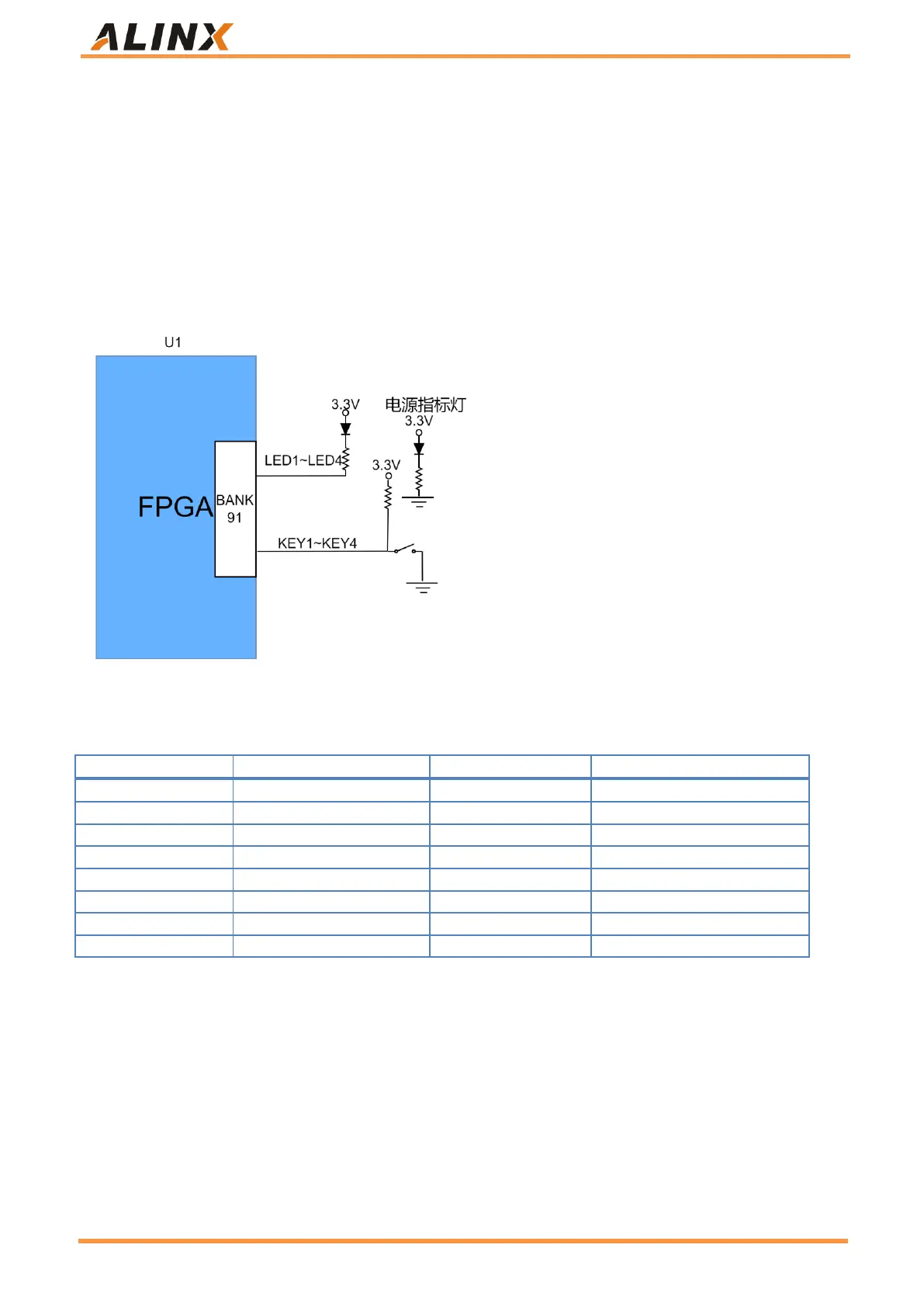
key level is low. Schematic diagram of hardware connection of user LED light and key is shown in Figure 26:
Figure 26: Schematic diagram of hardware connection of user LED light and key
Pin assignments for user LEDs and key:
Table 25: Pin assignments for user LEDs and key
Part 3.10: EEPROM
The AXP50 development board carries an EEPROM with a model of 24LC04 and a capacity of 4Kbit (2 * 256 * 8 bit),
which is composed of two 256 byte blocks and communicates through the IIC bus. The on-board EEPROM is to
learn how the IIC bus communicates. The I2C signal of the EEPROM is connected to the BANK B1 IO port of the
FPGA end. Figure 27 below shows the design of EEPROM.
 Loading...