www.en.alinx.com
www.en.alinx.com
Optical module 1 data sending minus 2
Optical module 1 data sending positive 2
Optical module 1 data sending minus 3
Optical module 1 data sending positive 3
Data transmission of optical module 1 minus 4
Optical module 1 data sending positive 4
BANK127 reference clock 0 negative
BANK127 reference clock 0 positive
BANK127 reference clock 1 negative
BANK127 reference clock 1 positive
I2C clock of optical module 1
I2C data of optical module 1
Interrupt signal of optical module 1
Low power consumption selection signal of
optical module 1
Optical module 1 presence indication signal
Module selection signal of optical module 1
Optical module 1 reset signal
Optical module 2 data reception minus 1
Optical module 2 data receiving positive 1
Optical module 2 data receiving negative 2
Optical module 2 data receiving positive 2
Optical module 2 data receiving negative 3
Optical module 2 data receiving positive 3
Optical module 2 data receiving negative 4
Optical module 2 data receiving positive 4
Optical module 2 data sending minus 1
Optical module 2 data sending positive 1
Optical module 2 data sending minus 2
Optical module 2 data sending positive 2
Optical module 2 data sending minus 3
Optical module 2 data sending positive 3
Data transmission of optical module 2 minus 4
Optical module 2 data sending positive 4
BANK128 reference clock 0 negative
BANK128 reference clock 0 positive
BANK128 reference clock 1 negative
BANK128 reference clock 1 positive
I2C clock of optical module 2
I2C data of optical module 2
Interrupt signal of optical module 2
Low power consumption selection signal of
optical module 2
Optical module 2 presence indication signal
Module selection signal of optical module 2
Reset signal of optical module 2
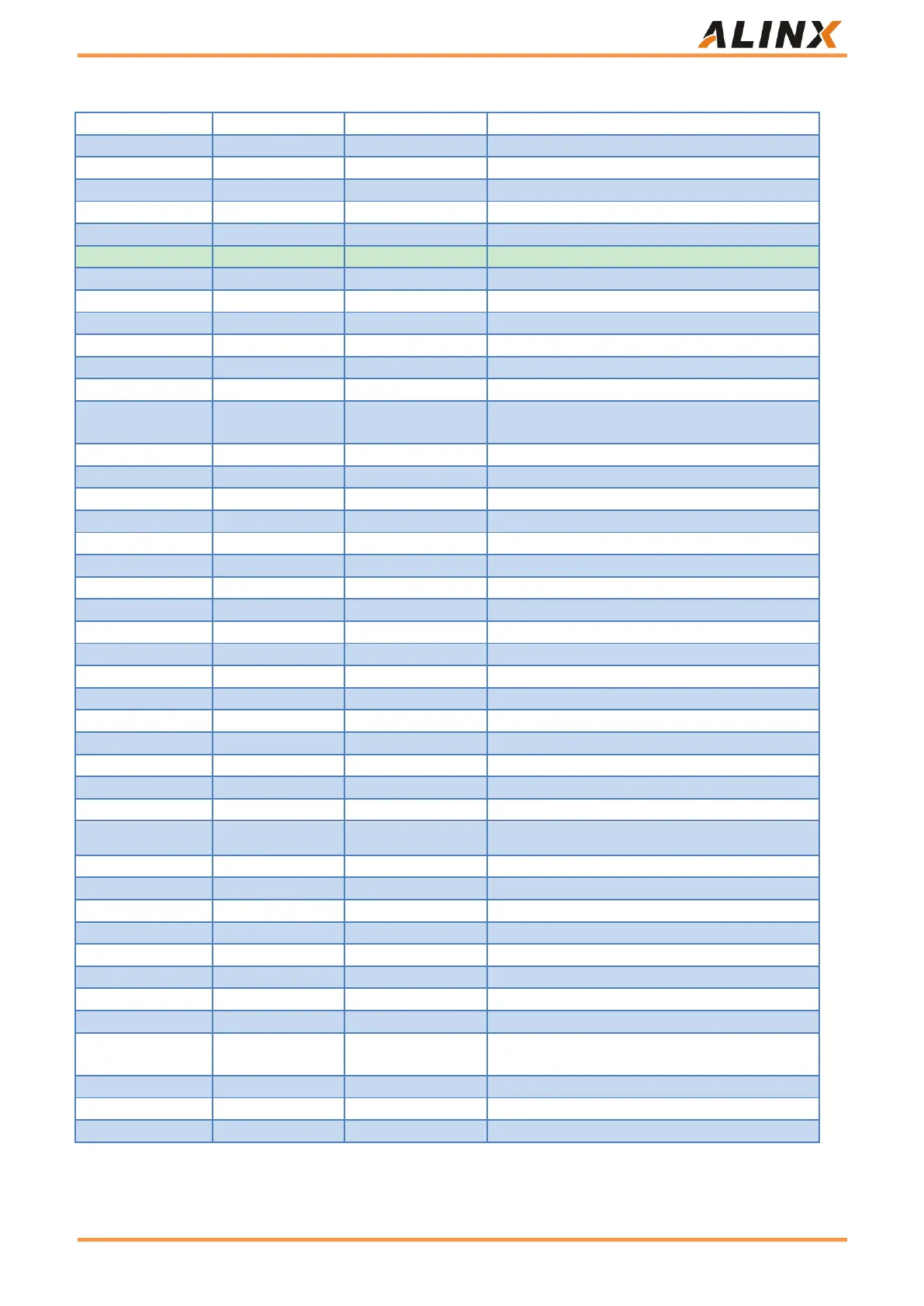
Table 28: optical interface pin assignment
 Loading...