ZYNQ Ultrascale + FPGA Board AXU4EV-E User Manual
Amazon Store: https://www.amazon.com/alinx
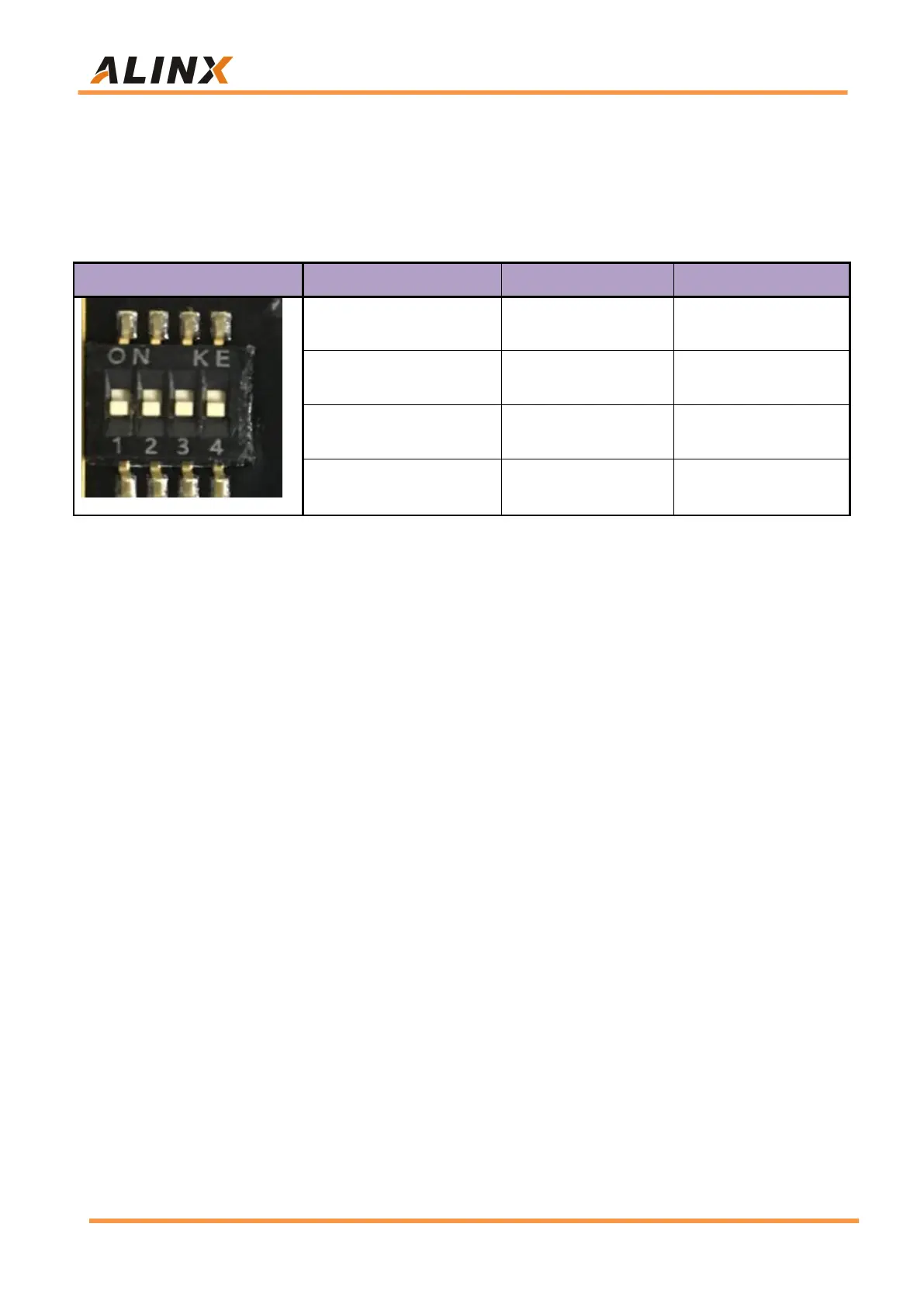
ZU4EV chip is powered on, it will detect the level of (PS_MODE0~3) to
determine the startup mode. The user can select different startup modes
through the DIP switch SW1 on the expansion board. The SW1 startup mode
configuration is shown in the following table 3-17-1.
Part 3.18: Power Supply
The power input voltage of the AXU4EV-E development board is DC12V.
In the carrier board, the DC12V is converted into +5V, +3.3V, and +1.8V
through one-way DC/DC power chip TPS54620 and two-way DC/DC power
chip MP1482. In addition, the Carrier board generates +1.2V through LDO to
supply power to the core board BANK65, and the power supply of BANK66 is
+1.8V. The schematic diagram of the power supply design on the board is
shown in Figure 3-18-1: