ZYNQ Ultrascale + FPGA Board AXU4EV-E User Manual
Amazon Store: https://www.amazon.com/alinx
Part 3.16: Keys
There are 1 reset KEY RESET and 2 user buttons on the AXU4EV-E
carrier board. The reset signal is connected to the reset chip input of the core
board ACU4EV, and the user can use this reset KEY to reset the ZYNQ system.
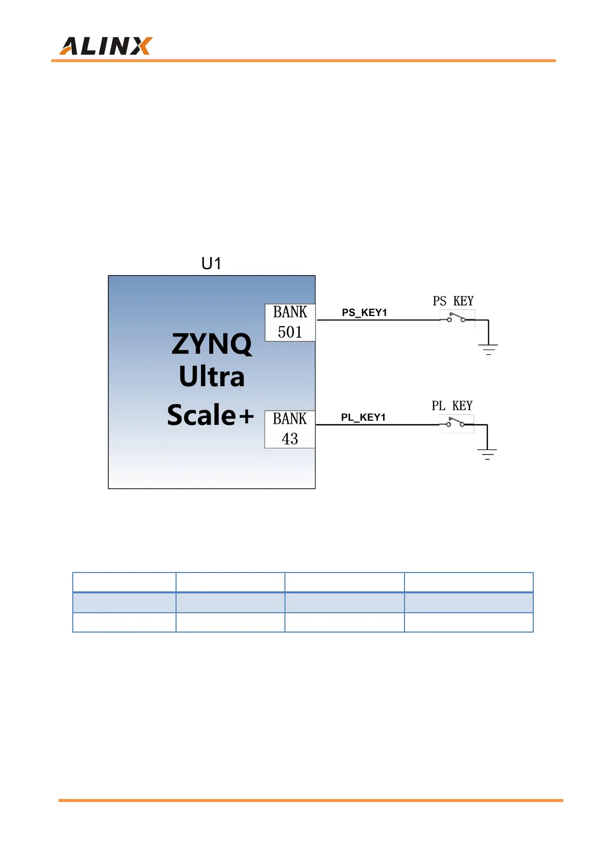
One user KEY is connected to the MIO of the PS, and one is connected to the
IO of the PL. The reset KEY and the user KEYs are both low-level active. The
connection diagram of the user key is shown in Figure 3-16-1:
Figure 3-16-1: Rest keys connection diagram
ZYNQ pin assignment of keys
Part 3.17: DIP Switch Configuration
There is a 4-digit DIP switch SW1 on the FPGA development board to
configure the startup mode of the ZYNQ system. The AXU4EV-E system
development platform supports 4 startup modes. The 4 startup modes are
JTAG debug mode, QSPI FLASH, EMMC and SD2.0 card startup mode. After