ZYNQ Ultrascale + FPGA Board AXU4EV-E User Manual
Amazon Store: https://www.amazon.com/alinx
Part 3.6: USB to Serial Port
The AXU4EV-E carrier board is equipped with two Uart to USB ports, one
is connected to the PS end, and one is connected to the PL end.
The conversion chip uses Silicon Labs CP2102GM's USB-UAR chip, and
the USB interface is a MINI USB interface. You can use a USB cable to
connect it to the PC's USB port for serial data communication. The schematic
diagram of the USB Uart circuit design is shown in the figure below:
The schematic diagram of the USB Uart circuit design is shown in Figure
3-6-1:
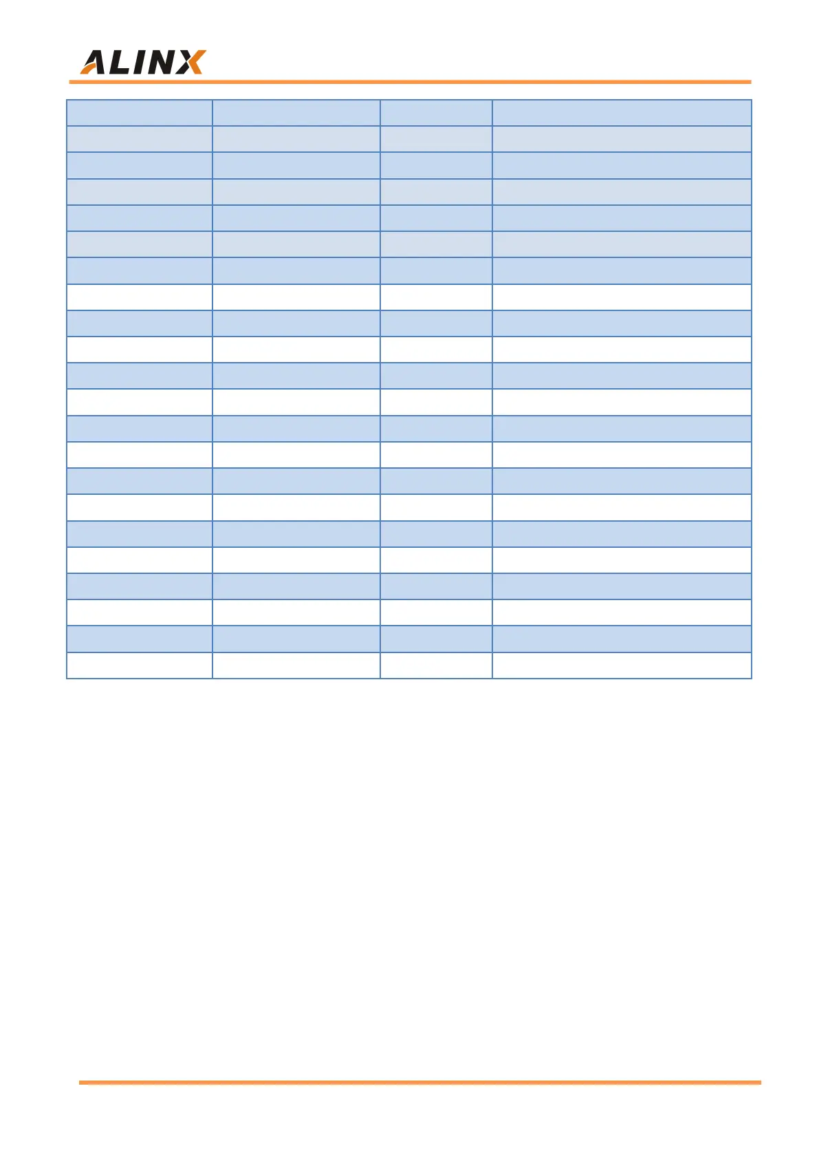
Ethernet 1 Receive Data Bit0
Ethernet 1 Receive Data Bit1
Ethernet 1 Receive Data Bit2
Ethernet 1 Receive Data Bit3
Ethernet 1 Receive Enable Signal
Ethernet 1 MDIO Clock Management
Ethernet 1 MDIO Management Data
Ethernet 2 RGMII Transmit Clock
Ethernet 2 Transmit data bit0
Ethernet 2 Transmit data bit1
Ethernet 2 Transmit data bit2
Ethernet 2 Transmit data bit3
Ethernet 2 Transmit Enable Signal
Ethernet 2 RGMII Receive Clock
Ethernet 2 Receive Data Bit0
Ethernet 2 Receive Data Bit1
Ethernet 2 Receive Data Bit2
Ethernet 2 Receive Data Bit3
Ethernet 2 Receive Enable Signal
Ethernet 2 MDIO Clock Management
Ethernet 2 MDIO Management Data