3–8 Installing the Module
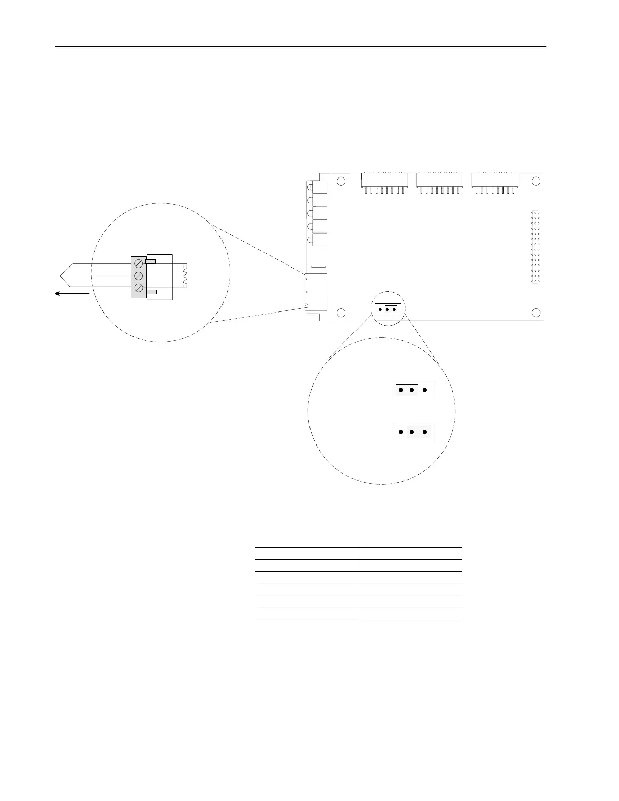
8. If the module is the last device on the Remote I/O link, either user
the internal termination resistor (J2) or an external termination
resistor. If the Remote I/O link uses 230Kbps, you must use an
external 82 ohm termination resistor.
Important:
Use only one type of termination (internal or external),
Figure 3.8 Using a Termination Resistor
9. Reapply power to the SCANport product.
10. Apply power to the Remote I/O link. The module is now
installed. Its LEDs are as follows:
You are now ready to create a ladder logic program.
Important:
If your LEDs are different, refer to Chapter 6.
J2
123
123
123
Not Last Device,
(Factory Default)
Last Device on link,
Termination
Resistor Inserted
Enables 150 ohm
Termination Resistor
Blue
Shield
Clear
To
Another
Remote I/O
Link Device
2
1
I50 Ohm
or
82 Ohm
1 watt
+/-10%
Sh
External Termination
Internal Termination
LED Status
Fault Red (Blinking)
SCANport STS Green or amber
➀ ➁
Health Green or amber
➁
Rem I/O ACT Off
Rem I/O STS Off
➀
This LED is off if the module use firmware 2.xx or lower.
➁
Early versions of the module use amber LEDs.
Artisan Scientific - Quality Instrumentation ... Guaranteed | (888) 88-SOURCE | www.artisan-scientific.com
 Loading...


