Home
Allen-Bradley
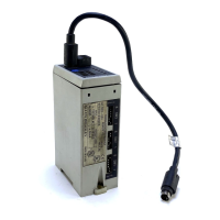
Control Unit
1203 Series
Allen-Bradley 1203 Series User Manual
4
of 1
of 1 rating
98 pages
Give review
Manual
Specs
To Next Page
To Next Page
To Previous Page
To Previous Page
Loading...
4
–
14
Creating Ladder Logic
Programs
End of Chap
ter 4
Artisan Scientific - Quality Instrumentation ... Guaranteed | (888) 88-SOURCE | www.artisan-scientific.com
52
54
Table of Contents
Default Chapter
6
Table of Contents
6
Audience for this Manual
8
Firmware Support
8
Preface Objectives
8
Purpose of this Manual
8
Terms and Abbreviations
8
Safety Precautions
10
Rockwell Automation Support
11
Chapter 1
12
Chapter Objectives
12
Description of the Remote I/O Communications Modules
12
Features of the Communications Module
13
Compatibility
14
Hardware Description
15
Required Tools and Equipment
17
Overview of Setting up the Module
17
Chapter 2
18
Chapter Objectives
18
Safety Precautions and Important Information
18
Locating the DIP Switches
19
Factory-Default Settings
20
Quick Configuration
20
Configuring the Module
20
Setting Switches on SW3
22
Setting Switches on SW2
26
Setting Switches on SW1
30
Chapter 3
32
Chapter Objectives
32
Selecting Cables
32
Selecting a Termination Resistor
33
Installing a 1203-GD1 or 1203-GK1 Module
34
Installing a 1336-GM1 Board
37
Chapter 4
40
Chapter Objectives
40
Understanding the I/O Image Table
40
Control Features
41
Datalinks
41
Settings for the Ladder Logic Program Examples
44
Example PLC Ladder Logic Program
47
Example SLC Ladder Logic Program
49
Example Logix5550 Ladder Logic Program
51
Chapter Objectives
54
Chapter 5
54
Understanding Block Transfer
54
Understanding the Block Transfer Status Word
55
Understanding Data Storage
56
Example PLC Block Transfers
56
Example SLC Block Transfers
58
Example Logix5550 Block Transfers
60
Notes Regarding Block Transfer Programming
61
Chapter 6
62
Chapter Objectives
62
Leds on the Remote I/O Communications Module
62
Fault Led
63
Scanport STS LED
63
Health LED
63
Rem I/O ACT LED
63
Rem I/O STS LED
63
Appendix A
64
Appendix Objectives
64
1336-GM1 Board Specifications
64
1203-GD1 Module Specifications
65
1203-GK1 Module Specifications
65
Appendix B
66
Appendix Objectives
66
Supported Block Transfer Messages
66
Block Transfer Data Structure
67
Parameter Value Read
68
Parameter Value Write
69
Parameter Read Full
70
Product ID Number Read
73
Scattered Parameter Value Read
75
Scattered Parameter Value Write
77
Continuous Parameter Value Read
79
Save/Recall/Initialize
81
Fault Command Write
82
Fault Queue Entry Read Full
83
Fault Queue Size Read
85
Trip Fault Queue Number Read
86
Block Transfer Quick Reference
87
4
Based on 1 rating
Ask a question
Give review
Questions and Answers:
Need help?
Do you have a question about the Allen-Bradley 1203 Series and is the answer not in the manual?
Ask a question
Allen-Bradley 1203 Series Specifications
General
Series
1203
Manufacturer
Allen-Bradley
Input Voltage
24V DC
Operating Temperature
0°C to 55°C
Housing Material
Plastic
Related product manuals
Allen-Bradley MicroLogix 1200
162 pages
Allen-Bradley 1756
42 pages
Allen-Bradley 160-DN2
116 pages
Allen-Bradley 1747-ASB
158 pages
Allen-Bradley 1756-IB16
258 pages
Allen-Bradley 1734-IE4S
235 pages
Allen-Bradley 1746-HSCE
23 pages
Allen-Bradley 1769-OF8C
32 pages
Allen-Bradley 1794-OA8K
24 pages
Allen-Bradley 1734-IB8S
235 pages
Allen-Bradley 1756-DHRIO
190 pages
Allen-Bradley 1756 Series
136 pages