14 Rockwell Automation Publication 1734-UM018D-EN-E - September 2017
Chapter 2 Install Your 1734 POINT I/O EtherNet/IP Adapter
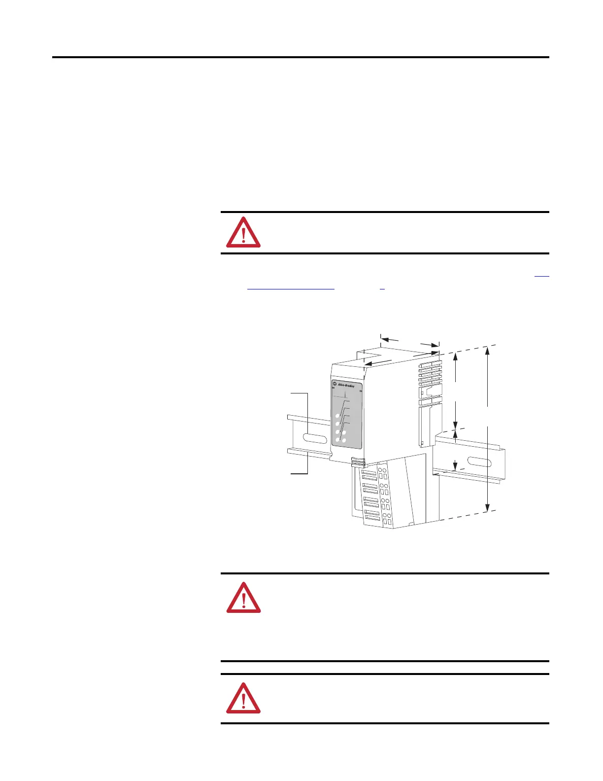
Mount the POINT I/O Adapter on a DIN Rail
1. Make sure the DIN rail locking screw (orange) is in horizontal position.
2. Position the adapter vertically above an IEC standard (35 x 7.5 x 1 mm)
top-hat DIN rail at a slight angle (DIN rail: Allen-Bradley part number
199-DR1; 46277-3).
3. Press down firmly to install the adapter on the DIN rail, noting that the
locking mechanism locks the adapter to the DIN rail.
4. Set the network address thumbwheel switches to the desired value. See Set
the Network Address in chapter 3 for details on setting the IP address.
5. Slide the safety end cap up to remove it, exposing the backplane and power
interconnections.
ATTENTION: Allow 25.4 mm (1.0 in.) of space between adjacent
equipment for adequate ventilation.
WARNING: If you connect or disconnect the communications cable
with power applied to this module or any device on the network, an
electrical arc can occur. This could cause an explosion in hazardous
location installations.
Be sure that power is removed or the area is nonhazardous before
proceeding.
ATTENTION: Do not remove or replace an Adapter Module while power
is applied. Interruption of the backplane can result in unintentional
operation or machine motion.
1734-AENT Series B
Module
Status
Network
Activity
Network
Status
Point Bus
Status
System
Power
Field
Po
w
e
r
POINT I O
75.30
(2.96)
74.00
(2.91)
132.72
(5.23)
52.23
(2.06)
35.55
(1.40)
A
B
45174
A = DIN rail
B = Secure DIN rail approximately every 200 mm (7.8 in.)

 Loading...