Remote I/O Adapter Module 11
Publication 1747-IN014C-EN-P - January 2003
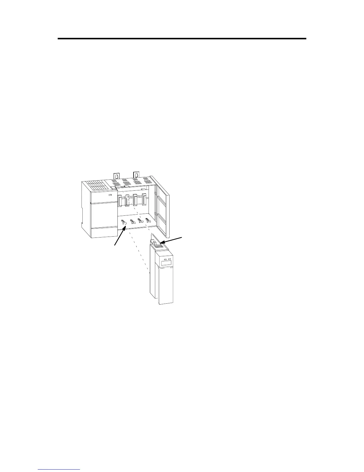
2. Install the module in slot 0 of the remote chassis by aligning the circuit
board with the chassis card guide.
The 1747-ASB module must be installed only in slot 0 (the left slot) of the
remote chassis. Do not install the 1747-ASB module in the remote expansion
chassis.
3. Slide the module into the chassis until the top and bottom tabs lock into
place. To remove the module, press and hold the release located on each
self-locking tab and slide the module out.
4. Cover all unused slots with the Card Slot Filler, Catalog Number 1746-N2.
Connecting RIO Link Devices
Link Wiring
The modules are connected in a daisy chain configuration on any RIO link. A daisy
chain network is formed by connecting network devices together in a serial manner
using Belden 9463 cable. Belden 9463 cable is the only approved cable for
Allen-Bradley RIO links.
The total number of adapters allowed on the RIO link is:
• 32 if the scanner and all adapters on the RIO link have extended node
capability
• 16 if the scanner or any adapter does not have extended node capability
Module Release
Card Guide

 Loading...


