14 Remote I/O Adapter Module
Publication 1747-IN014C-EN-P - January 2003
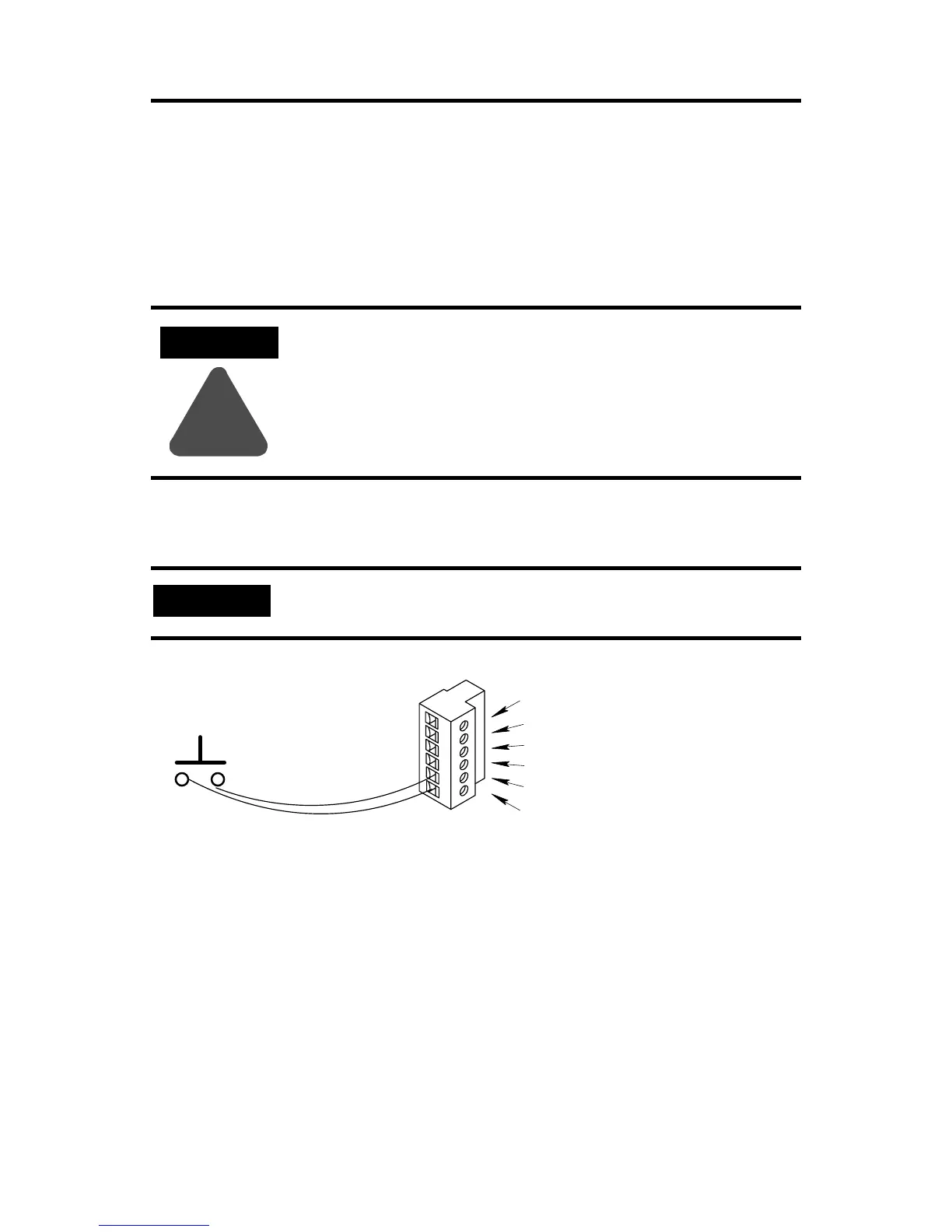
Wiring a Processor Restart Lockout Switch
When processor restart lockout is enabled (SW3-2) and communications are
restored, the 1747-ASB module does not respond to any type of communication, or
communication commands until terminals IN and RET are momentarily shorted
together. This occurs while the RIO scanner is attempting to communicate with the
1747-ASB module.
Use a momentary switch (Class 1, Division 2) to short terminals IN and RET
together. The processor restart lockout is removed as soon as the switch toggles
back to the open circuit position.
ATTENTION
!
Cycling power on any 1747-ASB module chassis removes the
processor restart lockout condition by re-initializing the
1747-ASB module.
IMPORTANT
Do not connect anything to the NC (No Connect) terminal.
Momentary Switch
14 - 24 gauge wire
(maximum 5 feet)
LINE 1 (Blue wire)
SHLD (Shield wire)
LINE 2 (Clear wire)
NC (No Connect)
IN
RET

 Loading...


