Remote I/O Adapter Module 13
Publication 1747-IN014C-EN-P - January 2003
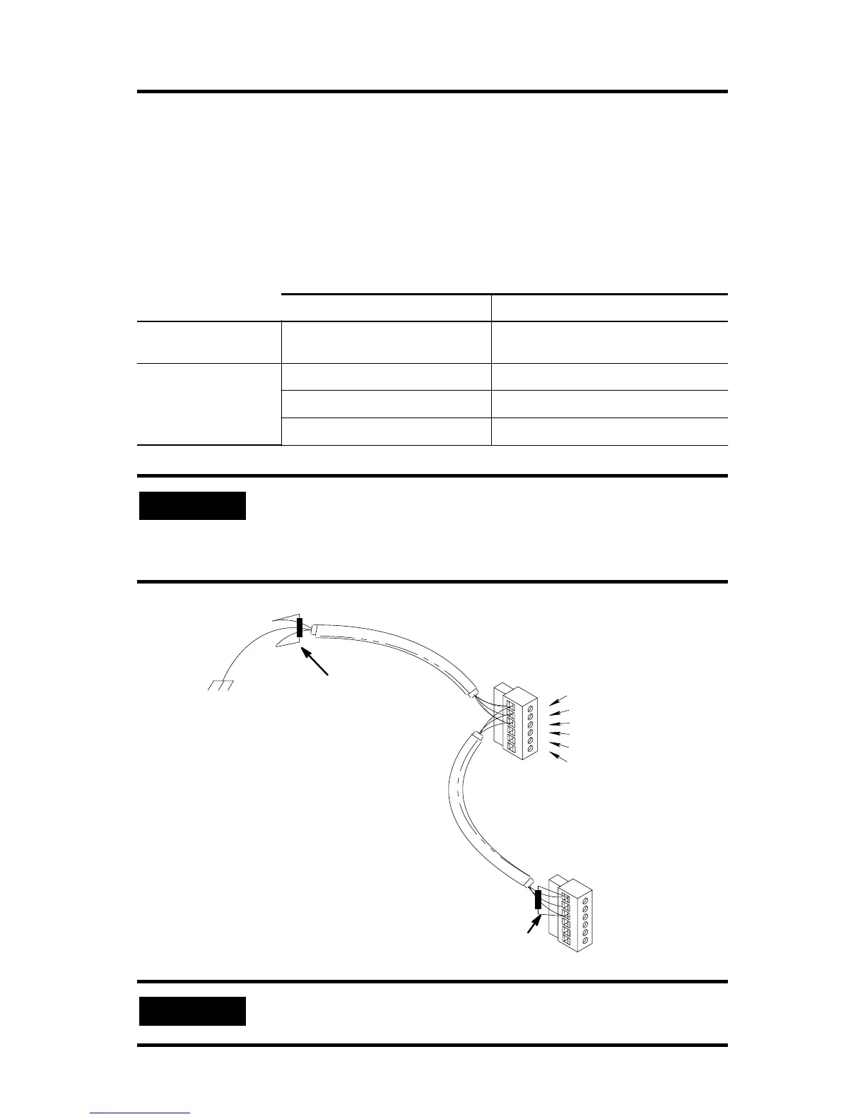
Link Termination
A 6-pin keyed connector provides a quick connection to the RIO link and processor
restart lockout switch. A user-supplied terminating resistor must be attached across
lines one and two of the connector at each end of the RIO link. The size of the
resistor depends on the baud rate and whether the scanner and all adapters have
extended node capability, as shown in the table below. The cable shield must be
connected to chassis ground only at one end of the RIO link.
Baud Rate Resistor size
Using Extended Node
Capability
All Baud Rates 82Ω 1/2 Watt
Not Using Extended
Node Capability
57.6K baud 150Ω 1/2 Watt
115.2K baud 150Ω 1/2 Watt
230.4K baud 82Ω 1/2 Watt
IMPORTANT
If the signal integrity on the RIO link is compromised by
environmental noise, improper termination, and/or improper
cable installation, the 1747-ASB module scan rate drops. This is
indicated by a pronounced flickering of the status display.
IMPORTANT
Do not connect anything to the NC (No Connect) terminal.
To Scanner’s
Connector
Chassis Ground
Terminating Resistor
Terminating Resistor
Blue
Shield
Clear
Line 1 (Blue Wire)
SHLD (Shield wire)
LINE 2 (Clear wire)
NC (No Connect)
IN
RET

 Loading...


