4 Remote I/O Adapter Module
Publication 1747-IN014C-EN-P - January 2003
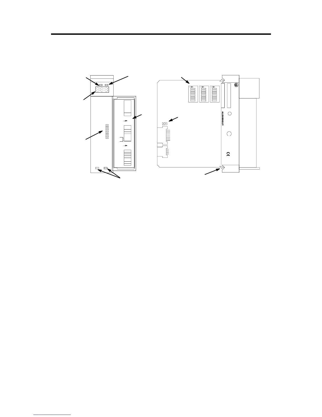
Hardware Features
Required Tools and Equipment
Have the following tools and equipment ready:
• medium blade screwdriver
• (2) 1/2 watt terminating resistors (See page 18 for correct size.)
• an adequate length of RIO communication cable (Belden™ 9463) for your
specific application. (See page 18 for maximum cable distances.)
Determining System Power Requirements
Review the power requirements of your system to ensure that the chassis supports
placement of the 1747-ASB module. The adapter consumes 600 mA at 5V dc. For a
detailed list of device load currents, refer to the SLC 500 Fixed Hardware Style
Installation and Operation Manual, publication number 1747-6.21; the SLC 500
Modular Hardware Style User Manual, publication number 1747-UM011, or the
appropriate Technical Data sheet.
U
FOR HAZ. LOC. A196
L
SLC 500
CAT SER
SERIAL NO. FRN
SA
ADAPTER
1 2 3 7 8
SW1
O
N
1 2 3 7 8
SW2
O
N
1 2 3 546
546
546
78
SW3
O
N
IMPORTANT :
INST ALL IN SLOT ZERO OF MODULAR CHASSIS ONL Y
REMOTE I/O ADAPTER MODULE
F AC 1M MADE IN USA
CURRENT REQUIREMENT : 375mA
LISTED IND. CONT . EQ.
CLASS 1, GROUPS A, B, C AND D, DIV . 2
OPERATING
TEMPERATURE
CODE T3C
1 23 45 6 7 8
SW1
1 2 3 4 5 6 7 8
SW2
1 2 3 456 7 8
SW3
O
N
O
N
LINE 1
SHLD
LINE 2
NC
IN
RET
(MSB)
LOGICAL
RACK
(LSB)
LOGICAL
GROUP
BAUD
RA TE
PRI/COMP
RSV
(MSB)
(LSB)
IMAGE
SIZE
HLS
PRL
RESP
LAST CHA
ADDR
MODE
SP MODE
KEY
1747-ASB
ST A TUS
COMM F AUL T
FAULT LED
(Red)
COMM LED
(Green)
Status
Display
Door
Label
Cable Tie Slots
Self-Locking Tab
DIP Switches
Manufacturing
Test Plug
RIO Link and
Processor
Restart
Lockout
Connector

 Loading...


