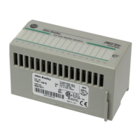
Remote I/O Adapter Module 5
Publication 1747-IN014C-EN-P - January 2003
Slot Addressing
Slot Numbering
The 1747-ASB module is capable of controlling 30 slots. When expansion chassis
are used, the 1747-ASB module treats all of the I/O modules as if they are installed
in a single chassis.
The remote chassis and remote expansion chassis slots are numbered from 0 to 30.
The 1747-ASB module must reside in slot 0. Slots numbered 31 and above cannot
be used.
Addressing I/O Modules
SLC and PLC processors address the I/O modules residing in the chassis by logical
rack and logical group. Slot addressing refers to how each chassis slot is assigned a
specific amount of the 1747-ASB module image. The amount depends on which
type of slot addressing you choose; 2-slot, 1-slot, and 1/2-slot addressing is
available, as shown below.
IMPORTANT
Installing modules in slot 31 or above results in a module error.
IMPORTANT
Due to SLC and PLC addressing differences, when the 1747-ASB
module is used with an SLC processor, the image bit numbers are
0 to 7, 8 to 15 decimal. When the 1747-ASB module is used with
a PLC processor, the image bit numbers are 0 to 7, 10 to 17 octal.

 Loading...


